

Over the past few years of testing MH lamps used in the hobby and attempting to characterize the light over the aquariums, one question that has often been at the back of my mind has been – How does the light over our aquariums compare to that on a natural reef? This article presents some data on the underwater light field on a reef and compares it to the artificial light field over our reef aquaria, along with discussion of other features of natural lighting that are often not simulated in our aquariums.
Surface Light Field
Before starting with the underwater light field, let us first take a quick short look at light field at the surface of the water along with the variations that are typically observed. The typical Photosynthetic Photon Flux Density (PPFD) at sea level on coral reefs on a clear sunny day have been measured at peak levels of 1600-2300 μEinstein/m2/s (Maritorena et al., 2002 . Typical variations result from several factors such as
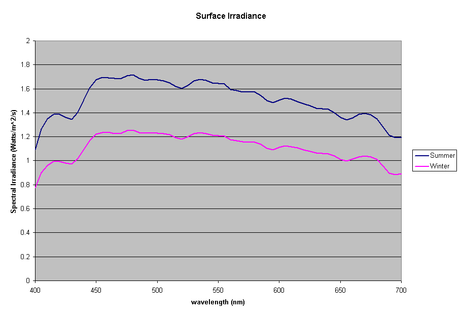
Figure 1: Spectral Irradiance at the surface of the water
- the daily variation from sunrise to sunset and the change in elevation of the sun’s path across the sky
- atmospheric factors such as scattering by air molecules and dust particles, absorption by water vapor and gases in the atmosphere
- level of cloud cover
- seasonal variation (variation between summer and winter). The diurnal variation is higher for higher latitudes.
Figure 1 shows the spectral output of the incident sun light over a Polynesian reef between the wavelengths of 400-700nm, the visible range and the range used to compute the PAR or Photosynthetic Photon Flux Density (data courtesy of S. Maritorena). The incident PPFD around noon for sunny days was typically around 2300 umoles/m2/s (500 watts/m2) in the summer and around 1600 umoles/m2/s (340 Watts/m2) in winter. The day length varied from 11-13 hours, with daily incident energy in the PAR range for clear skies increasing from 8.15 to 13.5 MJ/m2 between winter and summer.
Transmission Across the Air-Water Interface
The surface radiation at sea level enters the water at the air-water interface. Some of it gets reflected back (depending on the angle of incidence and the refractive index of water). Fresnel’s equation determines the amount the light reflected as a function of the angle of incidence and refractive index. The angle of incidence varies throughout the day as the sun moves across the sky. In addition, there are seasonal changes due to the movement of the sun between the two tropics. The angle of the sun impacts reef ecology – some reef organisms may be shaded during some part of the day, and in bright light during other parts of the day. This effect is more pronounced in shallower waters. At greater depths the direction of light becomes less sensitive to the sun’s position and moves toward the vertical as depth increases and is more diffused with depth. So, the direction of light reaching the deeper corals is relatively not affected by the change in the sun’s position. However, the intensity of light may change due to the relationship between the angle of incidence and refraction.
Fresnel’s equation:
where r = reflectance
θa = angle of incidence in air
θw = angle of the transmitted beam, determined by Snell’s law of refraction, and is given by θw =
θa /refractive index of sea water
From this equation it can be shown, that the reflectance remains low about 2-3.3% for zenith angles ranging from 0-60 degrees, and rising rapidly after it (see Figure 2). The zenith angle is the angle between the overhead point for an observer and an object such as the sun. The solar zenith angle is zero if the sun is directly overhead and is 90 degrees when the sun is on the horizon. So for most of the day, there is very little light lost due to reflectance at the air water interface if the sea is
relatively flat.
In reality, the water surface is not flat, it is usually roughened by the wind. However, this has very little effect on the reflectance of sunlight at high solar elevations. At lower elevations of the sun (sun on the horizon), the amount of photons reflected at the surface increases rapidly at angles greater than 60 degrees (measured from the vertical), the rough surface caused by the waves can lower such effect.

Figure 2: Reflectance of Light from Flat Water Surface
Surface waves also affect the light intensity. The waves can act as a lens and focus the light, creating “glitter lines.” These glitter lines appear as flashes of light of high intensity and short duration, and have been measured as having up to twice the intensity of light incident on the water surface (Falkowski et al., 1990). These glitter lines occurs only in direct sunlight, and do not occur when the light is diffused (as when a cloud obscures the sun). Whether this flashing light is advantageous to the corals or not is not known, but some researchers have found that it enhances photosynthetic performance in some unicellular algae (Falkowski et al. 1990). In reef aquariums, these glitter lines can be created through the use of point source lights (e.g., metal halide bulbs) and surface agitation of the water. Florescent lighting is more diffuse and does not create these effects. In an aquarium the light tends to be directed downward through the use of the reflectors and hence the angle of incidence is usually low. Thus we can expect the loss due to reflection of the water surface to be reasonably low, about 2-5%.
Underwater Light Field in Nature
Once the photons of light have made it all the way from the sun and across the air-water surface on the coral reefs, lets see what happens to them when they get into the water. The light traveling from the top of the water surface toward the bottom is called downwelling light. Some of the downwelling light gets absorbed, and some is scattered by the dissolved and particulate matter in the water and by the water molecules themselves. Turbidity is a term used to describe the amount of particulate matter. The higher the turbidity, the more light that is absorbed and scattered. The absorption and scattering result in reduction in the quantity of downwelling light as the depth increases (Kirk, 1994). Once the photons enters the water, most photos are eventually absorbed – either by the light absorbing molecules of the water, the optically active dissolved substances, the particulate matter, and eventually by the photosynthetic process that occurs in the corals and the suspended phytoplankton in the water column.
Further, the scatter also creates some upwelling light (backscattering of light). Some of this upwelling light escapes out of the water back into the air and is the reason for the color of the ocean. On coral reefs, the upwelling irradiance is also increased by reflection from the “white” calcium carbonate substrate found on the reef floor. In fact, on coral reefs this upwelling irradiance may be a significant portion of the total irradiance (Dustan 1982). This upwelling light plays a critical role in allowing the growth of corals on the under storey of the reefs. Thus, the addition of a white calcium carbonate substrate in a reef aquarium also helps in increasing the upwelling irradiance, while simultaneously increasing the biodiversity. Rather than covering all the sand with live rock, a good strategy would be to provide large open sand areas to increase upwelling irradiance.
Natural waters have what are often referred to as inherent and apparent optical properties. Inherent optical properties (IOP) are a function of the water and optically active substances in it and are not influenced by the geometric structure of the light fields. IOP were usually determined in the laboratory but now routinely measured in situ too and include the following (all units are m-1):
- absorption coefficient (a) – fraction of the incident flux absorbed divided by the thickness of an infinitesimally thin layer of medium
- scattering coefficient (b) – fraction of the incident flux scattered divided by the thickness of an infinitesimally thin layer of medium
- beam attenuation coefficient (c) – fraction of incident flux which is absorbed and scattered divided by the thickness of an infinitesimally thin layer. The beam attenuation coefficient is the sum of the absorption and scattering coefficients:
c = a + b
Apparent optical properties (AOP) are derived from measurements of natural light fields in a water body. They depend on the geometry of the light fields and are related to absorption and scattering. The most common of these properties is the diffuse attenuation coefficient for downwelling irradiance (Kd). Irradiance at a given depth (EZ) is a function of the irradiance at the surface (E0), the diffuse attenuation coefficient, and the depth interval (Z) according to the following relationship, where e is the base of the natural logarithms:
From this we can see that when light penetrates water its intensity decreases exponentially with increasing depth. The diffuse attenuation coefficient can thus be estimated by taking measurements at different depths, and using the above formula to compute Kd. The units for Kd are m-1.
Similarly to the absorption and scattering coefficients, the diffuse attenuation coefficient is not independent of wavelength, and is in fact different for different wavelengths. We can compute this value Kdλ for different wavelengths if we know the spectral curve at different depths. This spectral curve is usually obtained using an underwater spectroradiometer.
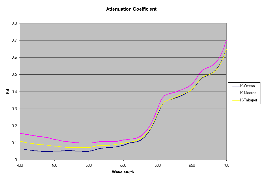
Figure 3: Diffuse Attentuation Coefficient for different waters
Using the data from the Ocean close to a high island in French Polynesia, lagoon of a high island (Moorea) and lagoon of an atoll (Takapoto), the diffuse attenuation coefficient for these 3 waters is shown in the figure 3 (Maritorena, 1996). As seen from this plot the 3 waters have slightly differing Kd values at different wavelengths. Higher Kd values imply that the light penetration will be less in that water.
As light passes through the water column, it is attenuated exponentially, and this attenuation is not uniform across all wavelengths. So the water acts as a “filter,” reducing the spectrum of light that penetrates it. As depth increases, the waveband of light that penetrates narrows. The shorter wavelengths (reds and yellows) are the first to be absorbed, and the blue light penetrates the deepest.
Using these diffuse attenuation coefficients (obtained from spectral irradiance measurements at different depths in the water), and using the fact that the attenuation in water decreases exponentially with respect to depth (given by the equation discussed earlier), we can plot the spectral curve for the underwater light field at various depths. Figure 4 shows the spectral distribution of light under water using the Kd values for clear ocean water during summer. The PPFD values corresponding to these spectral plots as a function of depth are given in the table below.
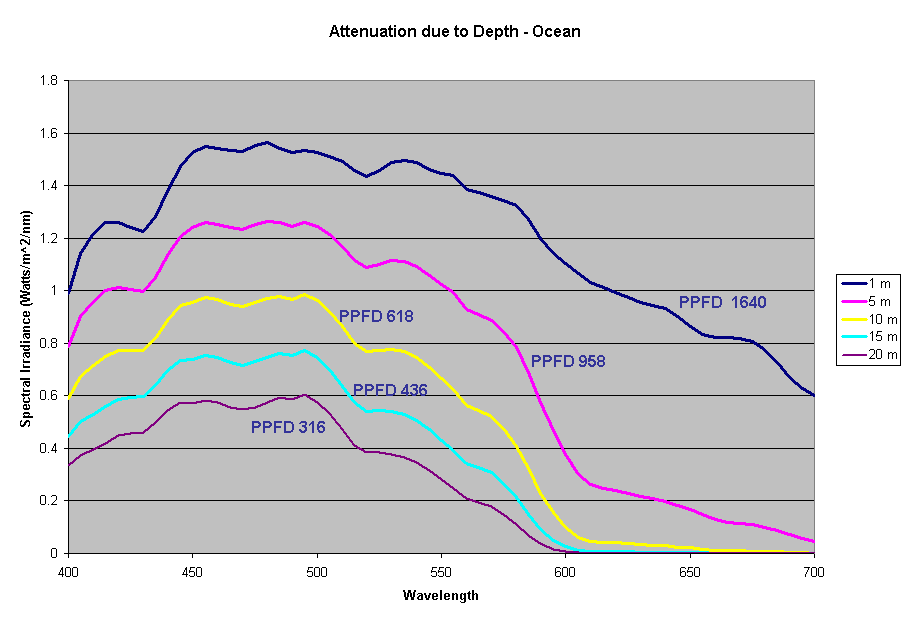
Figure 4: Spectral Distribution of Light Underwater at Different Depths
| 1m | 5m | 10m | 15m | 20m | |
|---|---|---|---|---|---|
| PPFD | 1640 | 958 | 618 | 436 | 316 |
Aquarium Light Field
Previous articles on spectral analysis of MH lamps and light distribution due to reflectors have provided data on the spectral characteristics and PAR of the existing light field over the aquarium. Taking 3 popular lamps that are representative of the 3 major classes of spectral distributions available to the aquarist: the 400W Iwasaki 6500K and the Ushio 400W 10000K and the Radium 400W 20000K, we can now make comparisons of these metal halide lamps to the natural light field under water. Keeping in mind that the change in intensity of a lamp only scales the spectral distribution, we can create spectral plots of PPFD equal to that of natural waters at different depths by scaling the spectral plots of these lamps.

Figure 5: Comparison of 400W 6500K Iwasaki to spectral distribution at varying depths
Figures 5,6 and 7 shows how the spectrums of the 3 metal halide lamps would compare to the natural waters for which the data is provided. As seen from figure 5, the Iwasaki 6500K provides a very good approximation of the spectrum underwater at a depth of 1m. At other depths the spectral irradiance at wavelengths less than 550 nm is less than natural water and higher than natural water at wavelengths greater than 550nm. For the 400W Ushio, it can be seen that at some wavelengths the intensity far exceeds that of natural light, in some cases by factors of 4-5 times what is observed in nature. The Radium shows almost 8-12 times the radiation at 454 nm than what would be observed in nature. Clearly other than the Iwaski which provides a good spectral match to the underwater light field at 1 m, there is a wide discrepancy in the spectral distribution of light over aquariums as compared to the natural light field.
An interesting question to ask is “What is the implication of this spectral discrepancy on the corals?”. I do not have any definitive answers but can speculate. Corals are highly adaptable in their ability to capture light and it is quite likely that they regulate the light harvesting pigments to adapt to the available light spectrum. This may possibly explain why wild corals change colors in our aquariums, or even why the coral color changes when grown under different light sources.
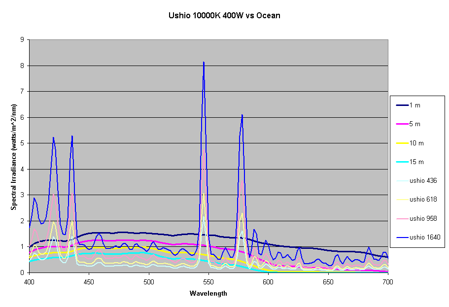
Figure 6: Comparison of 400W 10,000K Ushio to spectral distribution at varying depths
Effect of Water on the Light Field
Most of the SPS and other corals in our reefs are found in waters less than 15-20 meters deep, but our reef aquariums are usually only 24 to 30 inches deep. At this depth of water, the amount of light lost to absorption by the water is quite small. Using the diffuse coefficients for the ocean waters presented above, the amount of light at 700nm absorbed by 2ft of water is 33% of light just below the surface. For light at 400nm this is only 4%. So, we cannot rely on water to create large difference in spectral distribution in the tank and have to rely on the bulbs to provide a “correct” spectral distribution. Further more in our aquariums, the primary cause of light drop off is due to the “inverse square law”. This drop due to the distance from the source of light is much higher than the absorption in the water.
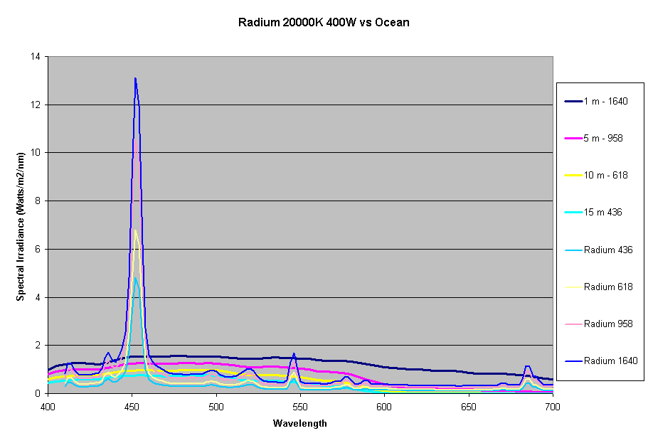
Figure 7: Comparison of 400W 20,000K Radium to spectral distribution at varying depths
Figure 8 shows the light attenuation at depths equal to 2 ft of aquarium water, assuming the Kd values for the ocean water.
Assuming the same Kd values, we can determine the change in spectrum of a metal halide lamp from the surface of the water to a depth of 2ft under water. Figure 9 shows the change in spectrum of the Iwasaki 6500K lamp just due to the water. In our reef aquariums this loss is quite small compared to the intensity loss due to distance from the lamp and reflector. For the Iwasaki lamp at 6″ from the water surface, the loss due to 2ft of water is about 14%, where as the loss due to the change in distance from the source (from 6″ to 30″) is about 70-90% based on the inverse square law of light and depending on the reflector being used. In practice this loss will be lower due to the additive effect due to multiple lights, but will still dominate the light loss as compared to loss due to attenuation in water assuming clear water similar to the ocean.
Other Comparisons of Natural Light to Aquarium Light
The amount of light and spectrum absorbed in the aquarium is often affected by the yellowing pigments or gilvin and the suspended particulate matter, and in fact may be higher than what we see in the ocean. The gilvin is typically made up of yellowing substance derived from humic acids from the decomposition of decaying plant material, run off from the terrestrial waters, breakdown of phytoplankton, etc (Jerlov, 1976). The absorption curve of gilvin follows an exponential curve with the absorption being the lowest in the red end of the spectrum and rising with decrease in wavelength towards the blue. Absorption is highest in the UV-A wavelength. The impact of this can be quite significant in an aquarium with yellowing water. Breakdown (and removal) of some of the gilvin through the use of activated carbon and ozone does, in fact, increase the irradiance transmitted through the water, especially in the UV range (Bingman 1996).

Figure 8: Attentuation of natural light at aquarium depth of 2ft
The light reaching the corals is not constant. This is one aspect of natural light that is not typically simulated in most of our aquariums. We typically subject the corals to almost constant light intensity with a fixed angle of incidence. The movement of the sun can be simulated to some extent through the use of light movers, which are available in the hydroponics gardening industry. Light movers that move light in a circular manner or linearly over rails may be used to provide the light variability throughout the day. However, given the fact that most home aquariums are less than 6 feet in length, the effect produced by moving the lights will not be as significant as in nature.
In addition to these variations, other natural variations are introduced by meteorological and biological events. The clouds over the reefs modulate the intensity of light. Storms may directly reduce the amount of light reaching the reef and may also stir up the substrate, increasing the turbidity and cutting off light reaching the corals. Seasonal plankton blooms can also increase turbidity of the water. Typically, most home aquariums do not simulate these variations, although some aquarists do introduce a “midday” cloud simulation by shutting off some of the lights randomly during the day for a short period of time. Other devices, such as light dimmers, are also becoming available. These devices will dim the lights to about 25-40 percent and can also be programmed to create this simulated cloud cover at various times during the day. Whether these variations are beneficial to the corals has not yet been established.
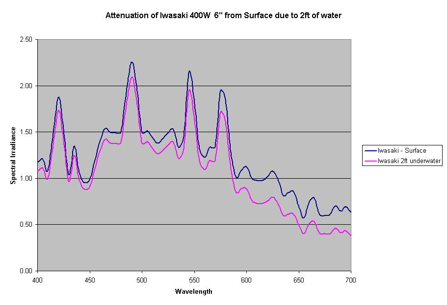
Figure 9: Attentuation of Ushio 4004W 6″ from the surface due to 2ft of water
Moonlight
The moon faithfully reflects the solar spectrum, so there is no change in the spectrum of light emanating from the moon. The intensity of solar radiation is about 500W/m2 while the intensity of full moon is about 1mW/m2 (1 milli Watt). Thus the intensity of a full moon is 0.5 Million times less that that of noon sunlight. Since the spectrum is the same as sunlight, the ocean waters will have the same diffuse attenuation coefficient for moonlight as sunlight. So even though the moon has the same spectrum of light as the sun the objects illuminated by moonlight lack color, primarily due to the low intensity of light and how the human eye responds at low light.
The reef aquarium industry and hobby has taken to using blue LED’s to simulate moonlight. Cleary this is very different from natural moonlight.
Conclusions
This article presented a comparison of natural underwater light (based on specific data from natural waters) to the light over our aquariums. While there are variations to be expected in natural waters, the general shape of the spectral distribution underwater will be quite similar. Clearly there is a wide discrepancy between the spectral irradiance provided by MH and the natural under water light field. We know from experience that we can grow coral under all the 3 major classes of metal halide lamps 6500K, 10000K and 20000K, so the corals must either adapt to the spectrum or ignore the spectral quality. Unfortunately I do not have any definitive answers to this, hopefully further research will be able to provide more definitive answers.
References
- Bingman, C. 1996. Quantitative relationships between visible water color and ultraviolet transmission. Aquarium Forntiers 3(4):12-16.
- Falkowski, P. G., P. L. Jokiel and R. A. Kinzie. 1990. Irradiance and corals. In Ecoystems of the World, Volume 25 Coral Reefs. Z. Dubinsky (Ed.):89-107.
- Jerlov, N. G. 1976. Marine Optics. Elsevier Scientific Pub., Amsterdam. Pp. 231.
- Kirk, J. T. 1994. Light And Photosynthesis In Aquatic Ecosystems, 2nd Edition. Cambridge University Press. Pp. 509.
- Maritorena, S. 1996. Remote sensing of the water attenuation in coral reefs : A case study in French Polynesia. Int. J. Remote Sensing , 17(1) : 155-166.
- Maritorena, S., C. Payri, M. Babin, H. Claustre, L. Bonnafous, A. Morel and M. Rodire. 2002. Photoacclimatization in the zooxanthellae of Pocillopora verrucosa and comparison with a pelagic algal community. Oceanologica Acta. 25(3-4): 125-134.

0 Comments