

Perhaps every reef hobbyist is willing to provide the “right” light to his corals – both correct spectrum and sufficient intensity are important. Before we consider how to implement this “right light,” we shall first try to understand what kind of light marine organisms get in their natural environment.
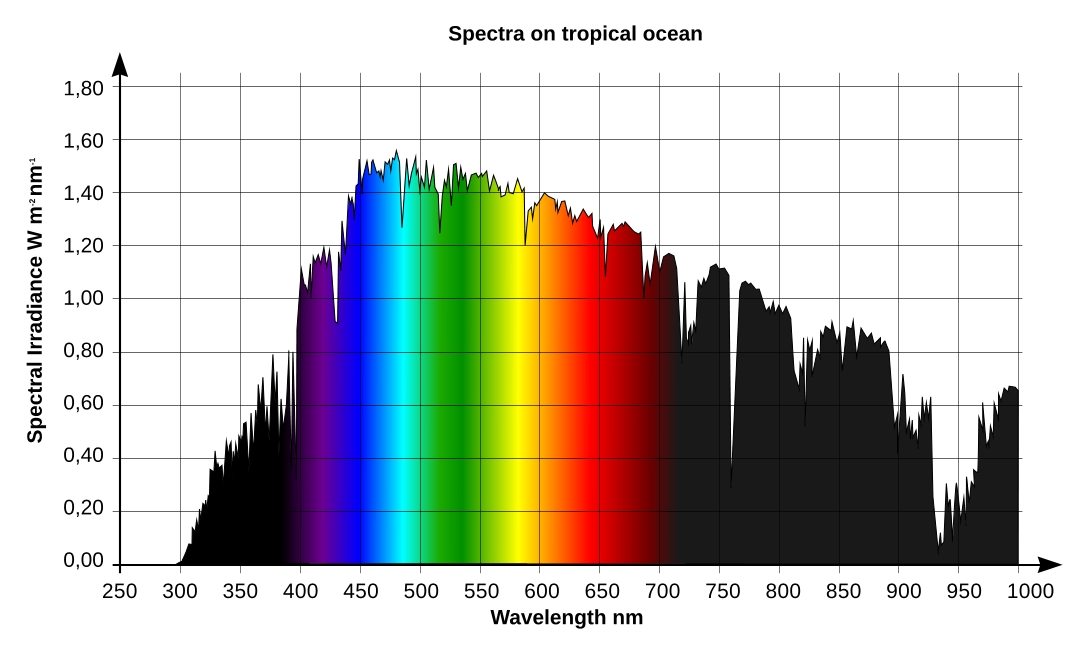
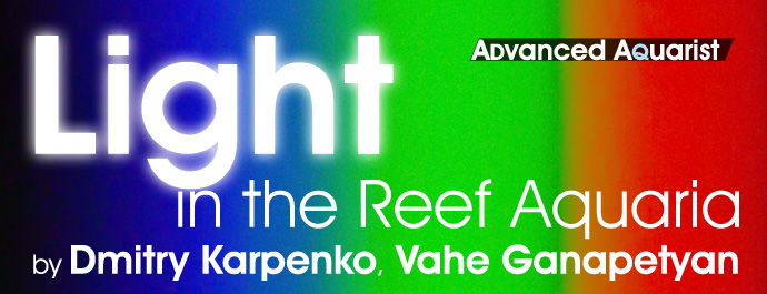
Fig. 1 Spectral distribution of sunlight energy at the level of the sea
As our starting point, consider the spectral distribution of solar energy in Fiji in July, Fig. 1:
The horizontal axis of the graph is wavelength, in nanometers, and the vertical axis is spectral irradiance, in W/m2·nm. The human eye is sensitive to radiation in the range between approximately 400 and 700nm, therefore we marked the wavelength ranges shorter than 400nm (ultraviolet light) or longer than 700nm (infrared radiation) in black, whereas visible wavelengths are colored as they are perceived by the eye.
The chart in Fig. 1 has been obtained from the solar spectrum at the boundary of the earth atmosphere using the SMARTS 2.9.5 scientific simulation software. This simulator takes into account light absorption by various components of the atmosphere as well as scattered light from the sky.
Let us now try to find out what kind of light spectrum is available to marine organisms in their natural environment. In our attempt to build an ideal light fixture for our reef tanks we shall try to generate a similar spectral distribution at certain depths underwater.
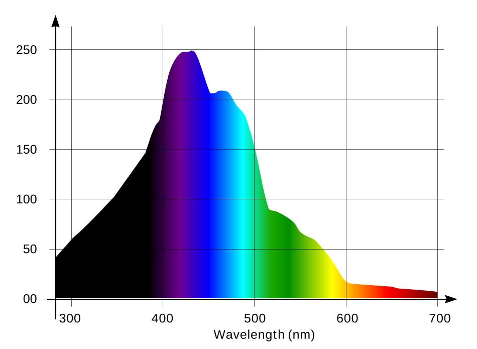
Fig. 2 Penetration of light into seawater, depending on wavelength
Different coral species live on various depths: some live in very shallow waters, whereas deep water corals, such as Bathypates spp., can be found on the depths of up to 8000 meters (about 5 miles). About 20% of all coral species are non photosynthetic; they do not require any light as a food source. Most corals, however, are photosynthetic, and these are the species which are kept most often at home aquaria. We shall try to figure out what kind of light they prefer.
Consider the graph of solar light penetration into marine water, depending on wavelength, compiled by the Institute for Environment and Sustainability of the European Commission [4] (Fig. 2):
The horizontal axis is the light wavelength, in nanometers, and the vertical axis is depth, in meters, at which the intensity of that wavelength is equal to one percent of the intensity at the surface. It is clear from this graph that wavelengths between approximately 370 and 500nm best penetrate into the depth. In other words, violet and blue parts of the spectrum penetrate best into seawater, whereas green light is much worse at that, yellow-orange is even worse, and red light with wavelengths longer than 600nm is only capable of penetrating very shallow waters.
The light spectrum on the surface can be defined as a function I0(λ), where λ is the wavelength and I0 is the intensity for corresponding wavelength at zero depth. Hence the adsorption spectrum Ia(λ) at the depth D can be determined as
Ia(λ) = I0(λ) · K(λ) · D (1)
where K(λ) is the adsorption by marine water as a function of wavelength.
The spectrum at the depth D will be equal to the spectrum on the surface I0(λ) minus the adsorption spectrum Ia(λ):
I(λ) = I0(λ) – Ia(λ),
or, by substituting (1) into this expression, we shall derive:
I(λ) = I0(λ) · (1 – K(λ) · D) (2)
From this expression we can derive the graph of light penetration into seawater d(λ):
d(λ) = (1 – I(λ) / I0(λ)) / K(λ)) (3)
Providing that the graph in Fig. 2 is based on the assumption that light intensity on the specified depth is equal to 1% of the intensity on the surface, i.e. I(λ) = 0,01 · I0(λ), we can simplify (3):
d(λ) = 0.99 / K(λ)
This function d(λ) is our graph of light penetration into seawater, which is pictured in Fig. 2. Using this graph we can determine light adsorption in seawater as a function of wavelength K(λ):
K(λ) = 0.99 / d(λ) (4)
By substituting the expression (4) into (2), we can derive the spectral distribution of light at a given depth D:
I(λ) = I0(λ) · (1 – 0.99 · D / d(λ)) (5)
where I0(λ) is the light spectrum on the surface and d(λ) is the graph of light penetration into seawater (Fig. 2).
Fig. 3 Light spectral distribution vs. wavelength on the surface (light blue), at 5m (blue) and 15m (dark blue) depths
Using the expression (5) and the data from graphs in Fig. 1 and Fig. 2, we can obtain the diagram of light energy distribution vs. wavelength at a given depth. As an example, on the same graph (Fig. 3) we pictured light’s relative spectral distribution at the surface and at the depths of 5m (about 16.4 feet) and 15m (49 feet). Note: 15m is the maximum depth at which we can still find many light-demanding corals in nature. At the depths below 20m, the number of light demanding species sharply decreases.
The light-blue graph corresponds to irradiation on the surface, the blue graph – to 5m depth, and the dark-blue – to 15m depth. Note that with depth, the red part of the spectrum virtually disappears.
During hundreds of millions years of evolution marine photosynthetic organisms adapted to best utilize mainly the violet and blue parts of the spectrum, which is more abundant in their environment, and are not very sensitive to the red spectrum (which, in contrast, is most actively utilized by terrestrial plants). Symbiotic zooxanthellae in marine photosynthetic organisms are primitive Pyrrophyta algae [5] containing mainly chlorophyll a and c and carotenoid pigments (peridinine, xanthins, etc) which exhibit strong absorption in the blue-green part of the spectrum. [6,7,22]. Fig. 4 [22] demonstrates light adsorption by zooxanthellae.
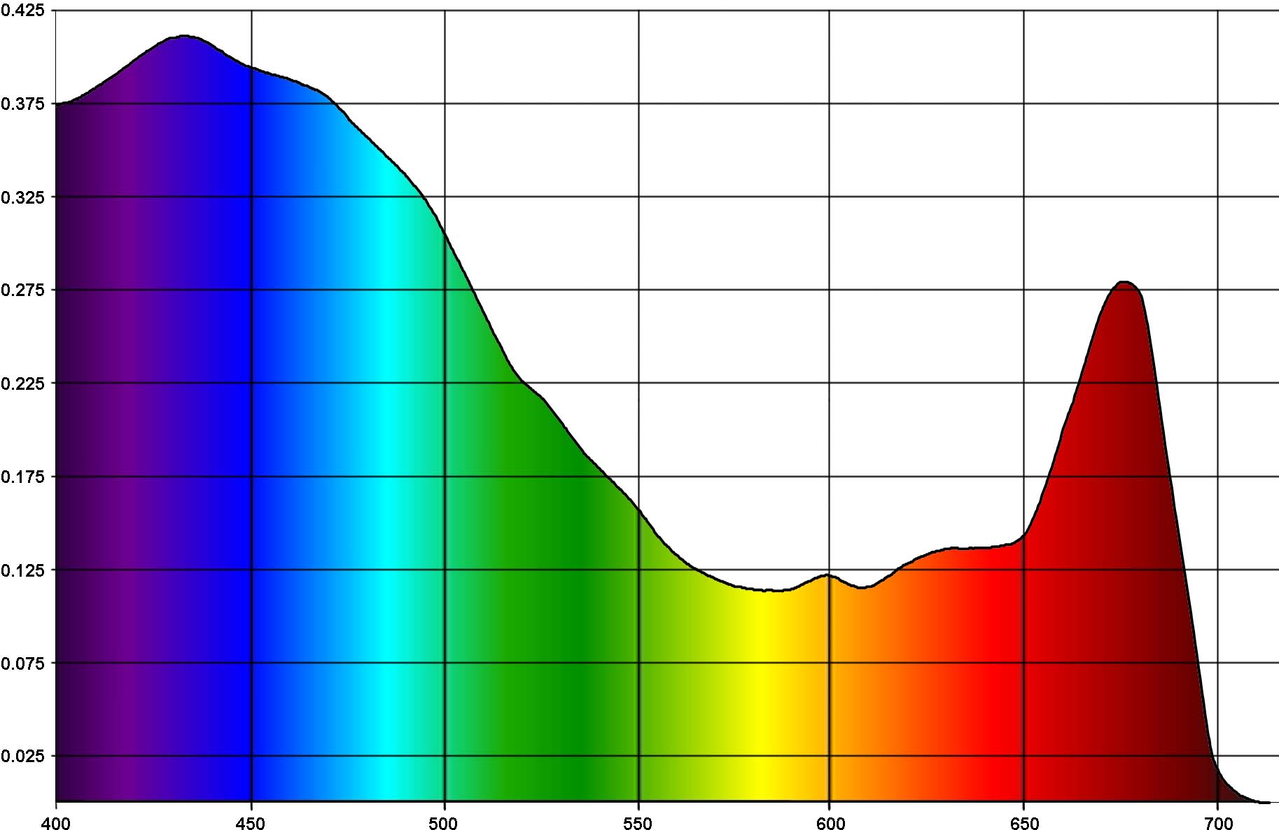
Fig. 4 Light absorption by zooxanthellae
The horizontal axis is the wavelength, in nanometers, and vertical axis is adsorption, in arbitrary units. You can see from the graph that violet and blue colors strongly prevail over red (note that for red spectrum, the 660-680nm range is preferable).
Our main conclusion from the above is that violet and blue light are most important for marine photosynthetic organisms.
Knowing what is naturally available to corals from the color spectrum, we shall now consider the next important issue: how irradiation by different spectral ranges affects coral coloration?
Before we consider the influence of the light spectrum on coral coloration I would like to point out that even coloration of the same coral may vary significantly depending on conditions. Unfortunately, it is very difficult to provide exactly identical conditions for the corals, even in the same aquarium – and this is even harder for two different tanks. Without providing the right conditions for the corals, other attempts to improve their coloration, such as adjustments of the light spectrum, will be in vain.
Experienced reef keepers well know how variable the coloration of the same coral can be in different conditions. There are three main factors which affect it most: light spectrum and intensity, the amount of food available in water (although coral polyps receive a significant portion of their energy from the zooxanthellae, they are also able to capture food particles from the water column), and from the purity of the water. This last factor is easiest to control: techniques to maintain pristine water in reef aquaria are well known. The second factor, too, can be solved easily since there are a number of quality coral foods readily available on the market. At the same time many aquarists believe that, if there are fish living in a reef aquarium, corals will get sufficient food from small particles which float around from feeding the fish (and fish poo too is consumed by corals).
Light is the last important factor required for good health and the coloration of corals, and yet has not been studied sufficiently well in reef keeping.
The situation is rather complex though, since corals can be very variable, and even the same species may contain different chromoproteins (proteins responsible for coloration) – their type and amount are also determined genetically, in the same way as, say, the color of human’s eyes. Many of these proteins are fluorescent; i.e., they adsorb the light of a certain wavelength and radiate a different wavelength.
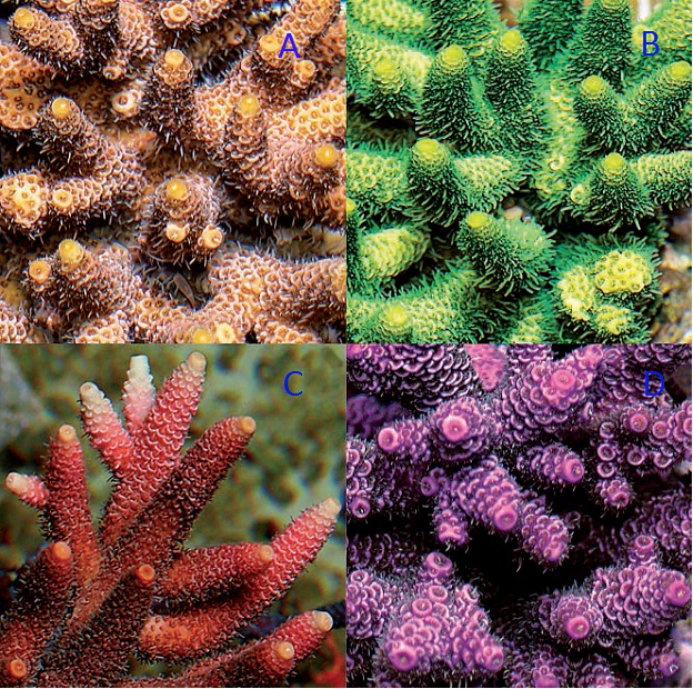
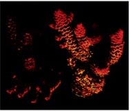
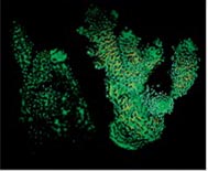
Fig. 5 The Acropora millepora specimens with different prevailing chromoproteins: (A) low concentration of chromoproteins, the color of zooxanthellae dominates; (B) green fluorescent proteins; (C) red fluorescent proteins; (D) non-fluorescent chromoproteins. Image courtesy of Dr. C. D’Angelo and Dr. J. Wiedenmann, University of Southampton, UK, Coral Magazine, Nov./Dec. 2011
Fig. 5 shows four specimens of the same species, Acropora millepora, in which different chromoproteins prevail:
Fluorescence is witnessed not only in hard corals but, for example, in Zoanthidae and Palythoya polyps which exhibit much brighter coloration when irradiated with so-called short-wavelength “actinic” light.
Coral fluorescence is very beautiful but it is not always easy to observe it. Have a look at the luminous function (spectral sensitivity chart) of the human eye (Fig. 6). Light sensitive elements of the eye are represented by two cell types – the so-called retinal cones and rods. The first are responsible for distinguishing between colors, and the second – for grey tones. The cones work best during daytime, the rods – at night. Remember the saying “all cats are grey in the dark.” This is just because we mainly see with the rods in the dark, rather than with cones. The rods do not distinguish between colors: they only sense the relative brightness of an object. The rods are most sensitive to the emerald-green part of the spectrum, with the wavelength of about 510nm (of course, when seeing by the rods, this light is only perceived as a brighter shade of gray rather than green.
There are three cell types in cones, each sensitive to a specific part of the spectrum. S-type cones are sensitive to violet and blue (S stands for Short wavelengths), M-type – for green and yellow (Medium wavelengths), and L-type – for orange and red (Long wavelengths). These three cone types, (along with the rods that are sensitive in the emerald-green part of the spectrum) are responsible for color vision in humans. The rods contain a color-sensitive pigment, rhodopsin, and their spectral characteristic depends on lighting conditions. For weak light, rhodopsin’s adsorption peak is at about 510nm (the spectrum of the sky at twilight). And therefore the rods are responsible for twilight vision, when colors are hard to distinguish. At higher levels of illumination rhodopsin photo bleaches, and its sensitivity decreases, while the adsorption peak shifts into the blue region. As a result, under sufficient light, the human eye can use the rods as a shortwave (blue) light detector. S-cells are sensitive in the 400-500nm range with a maximum at 420-440nm; M-cells are sensitive in 460-630nm range, with a maximum at 534-555nm; L-cells are sensitive in the 500-700nm range with a maximum at 564-580nm [1]. Sensitivity ranges of long- and medium-wavelength cones are wide and overlapping. Therefore it is wrong to think that certain cone types only react to certain colors – they just more actively react to certain colors than to others [2]. The human eye is most sensitive in the range where sensitivities of M- and L-type cones add up: at 555nm (yellow-green light). The overall spectral sensitivity function [3] of human eye receptors is shown in Fig. 6.
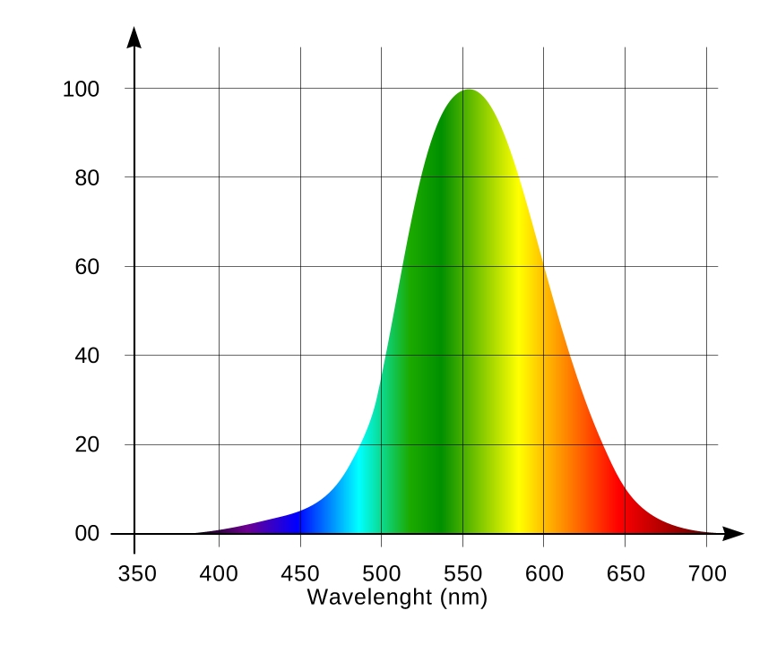
Fig. 6 Luminous function of the eye
An important conclusion here is that the human eye sensitivity to light depends on the wavelength. For example, radiation of equal power is perceived 27 times brighter for the 555nm wavelength than for 450nm; this difference increases to 57 times for 420nm, and 135 times (!) for 410nm.
Humans visually perceive any object as the sum of its reflected light and the object’s intrinsic emission (an object is considered light emitting if its total emission at a certain wavelength range is higher than the falling light energy in that same region). Usually objects only reflect light, and their color is determined by the ratio, in which different wavelengths falling on its surface are adsorbed or reflected. For example, green leaves adsorb all visible wavelengths except for green, which is reflected – therefore we perceive it as green. When an object not only reflects but also emits its own light, the eye combines the emitted and reflected light spectrum into its perceived color. Yielding color depends on the ratio of the intensities and wavelengths of both reflected and emitted light. This color addition is best illustrated by the diagram shown in Fig. 7:
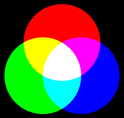
Fig. 7 Additive color mixing
When looking at the computer monitor, you witness the effects illustrated by this chart: every pixel on the screen consists of three sub pixels: red, green and blue, and all colors are obtained by combination of their intensities.
Note that pure purple color and its tints, such as magenta or fuchsia, are unique in being non-spectral or extra-spectral: there is no specific wavelength associated with these colors, they are mixtures, and one of the required components is violet, with the wavelength around 400nm [13], and red. If a specific light source has no radiation in this range, up to 20% of the whole color palette is lost – and these are very bright colors and their shades! It is also interesting to note that by combining the yellow and blue colors the resulting color is visually perceived as pure white.
Color vision is mainly inherited genetically. We are not talking about the defects of color vision, such as color blindness – but each person perceives colors in his own way, and this difference can be very significant. Apparently, it is very important to be able to adjust the spectral distribution of the light fixture, to find an individually suitable color distribution in the reef tank.
To watch coral fluorescence we shall irradiate the fluorescent proteins with light of a specific wavelength. Look at the adsorption and radiation wavelengths chart for most common fluorescent pigments available in marine organisms [9], shown in Fig. 8.
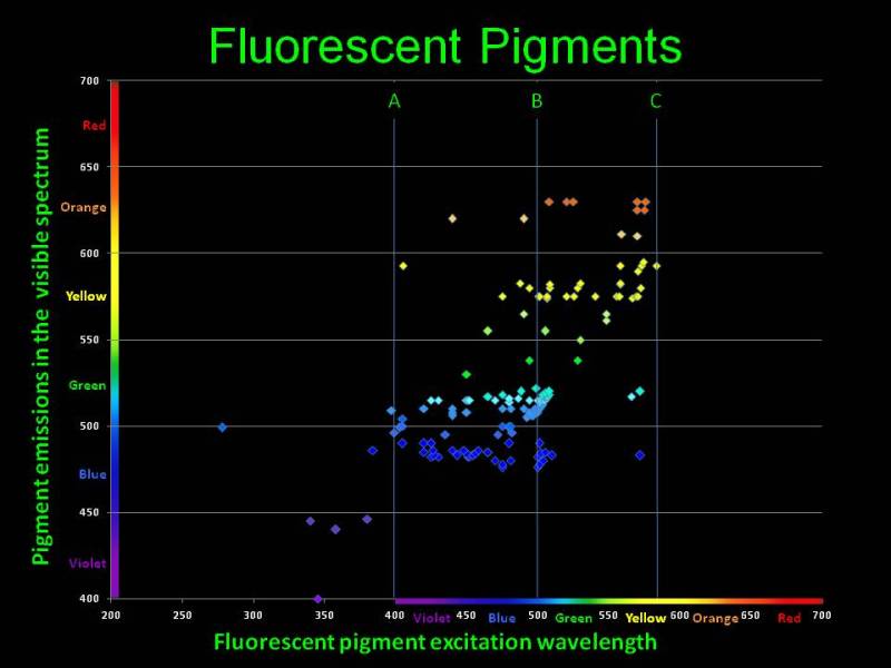
Fig. 8 Adsorption and emission wavelengths for fluorescent pigments available in marine organisms. The figure is courtesy of Dan Kelley
The horizontal axis are the wavelengths which cause fluorescence in various chromoproteins; the vertical axis is the wavelength emitted as a result of fluorescence. You can see that virtually all pigments adsorb shorter wavelengths and emit longer wavelengths. As we have shown above, the eye is most susceptible to the 550nm range, and the closer the emitted light is to that wavelength, the brighter it will be perceived. Thus, specific proteins available in marine organisms adsorb the poorly visible to the eye short wavelengths and fluoresce with a color which looks much brighter to our eye. Under purely “actinic” light, which only contains shorter wavelengths, our fish tank will glow with bright colors, whereas the light from the fixture itself is almost invisible to the eye. This gives the impression of miniature light bulbs installed in each coral or polyp, which glow brightly in the dark!
Color of a coral, as perceived by the eye, also depends on the color of falling light. The color of any object that we see represents the reflected portion of the falling light spectrum. As we have pointed out above, when illuminated by a full-spectrum light, the leaves of most terrestrial plants adsorb almost all parts of the visible spectrum, and reflect the green part – therefore we perceive them as green. However, if we irradiate the leaves by a light in which the green part of the spectrum is missing – by red light, for example – they will seem black to us, because all falling light is adsorbed. In a similar manner, white object looks white under full spectral light, because it uniformly reflects all parts of the spectrum, but will “take up” the color of any light that we throw at it: red, green, blue, or their combination.
Back to corals – let us consider an organism containing a protein which, when irradiated by the 420nm light, will fluoresce by the 520nm wavelength. For reasons of simplicity, suppose that our light source radiates only at the 420nm wavelength, and the coral adsorbs this light completely, without reflection. The human eye has extremely low sensitivity to this wavelength (almost invisible), whereas it is most sensitive to the wavelength radiated by the coral as a result of fluorescence. We shall see this fluorescence very well in the “dark” pure actinic light. If the light source includes radiation at other wavelengths, the resulting color of the marine organism will be added up from fluorescence and reflected light. If the light source contains wavelengths, to which the eye is very sensitive (especially in close proximity to the 550nm sensitivity peak), we will mainly see the light from the fixture, and perception of coral fluorescence will be weak on this bright background.
Our conclusion is that for best observation of fluorescence, we shall illuminate the tank with such light that its reflected portion would least hinder us in seeing the light radiated by corals. Wavelengths required for fluorescence of all chromoproteins are numerous, and there is no single wavelength that could be used for making an ideal actinic light. Based on Fig. 8, fluorescence is observed in quite wide a range of falling light wavelengths, mainly between 400 and 500nm, and different organisms have different fluorescent protein sets. For best fluorescence we need the capacity to adjust the light spectrum in the 400 to 500nm range, according to the needs of a particular aquarium.
Note that the strongest fluorescence will be observed in 400-450nm range, particularly because the eye sensitivity in that range is very low. The light in this range is usually called “actinic light.”
Surely, coral fluorescence is one of the main factors to provide a reef tank’s beauty, but the light in the 400-500nm range also has other importance: it is the most optimal light to promote marine photosynthesis. Therefore this part of the spectrum is of utmost importance for a reef tank.
This conclusion matches well with the experimental research in this field [16]. Fragments of Acropora millepora colony were maintained for six weeks under comparable amounts of red, green, and blue light. The conclusion of the article is that “the enhancement of coral pigmentation is primarily dependent on the blue component of the spectrum and regulated at the transcriptional level,” and “light-driven accumulation of GFP-like proteins observed upon green light exposure is likely due to residual blue light passing the green filter.” The experiments also revealed that radiation in the 430nm range is most efficient in promoting the protective bright coloration of the corals:”Among the known FPs and CPs, only the absorption properties of CFPs spectrally match the major absorption band of chlorophyll a and c at ~430 nm, making them suitable for effective shielding of the photosynthetic system of the zooxanthellae.”
The intensity of light is also very important for growth and active production of fluorescent chromoproteins.
A light source could be best characterized, perhaps, by spectral distribution of the optical radiation energy at different wavelengths. This characteristic is usually represented by the spectral curve. For most common light sources, however, the spectral characteristic is usually unavailable, and instead an estimated light flux is provided, in lumens.
Light flux in lumens is the visible light radiation power, as perceived by the human eye – depending on the eye’s sensitivity to different wavelengths. Note: One lumen is the total luminous flux emitted uniformly by a light source with luminous intensity of one candela across a solid angle of one steradian (a cone with the angle of approximately 65.5° at the apex). Candela is the luminous intensity, in a given direction, of a source that emits monochromatic radiation of 555nm wavelength (i.e. the wavelength at the peak sensitivity of the human eye), and has a radiant intensity in that direction of 1/683 watt per steradian.
One watt of optical power radiated at the 555nm wavelength corresponds to 683 lm. For any other wavelengths, it is equal to the optical power emitted at that wavelength multiplied by the luminosity function of the eye for the same wavelength. To determine total lumens emitted by a light source we need to sum up the lumens for all emitted wavelengths.
It is evident that the intensity equal light energy in various parts of the spectrum will be perceived differently by the eye: a powerful source in the 400-450nm range will be perceived as very dim light, and a light source emitting in the infrared region will seem black. Therefore an estimate of the light flux in lumens is only valid when light’s spectral distribution is unimportant and the only thing that matters is brightness, as perceived by the eye.
In our case, a more appropriate parameter for determination of light radiation would be the number of photons per second, falling on each meter square: μmol·photons/m2/s.
During the hundreds of millions years of evolution marine photosynthetic organisms adapted to different light power levels. For each photosynthetic organism three threshold values can be defined [14]. First (least intensive) determines the minimum light required for the maintenance of photosynthetic organism’s biomass – it is the minimum required light which will not result in gain or loss of mass. The second threshold value concerns illumination at which the photosynthesis efficiency is highest. And finally the third, upper threshold is the maximum light which can be utilized -there is no improvement in photosynthesis rate above that threshold. These three thresholds, of course, depend on particular organisms, but we can use an estimate for marine photosynthetic organisms living in shallow waters. We can safely call 80-100 μmol·photons/m2/s low light, 150-200 – medium, and 300-400 – optimal. The saturation limit of photosynthesis is about 600-700μmol·photons/m2/s.
In our reef tank, we shall achieve a significantly better illumination than the minimum threshold – preferably near the optimal threshold.
Let us consider yet another experiment with Acropora millepora to illustrate the production of chromo proteins under less than optimal illumination, and when the light level is in optimal value for the species (Fig.9).
| Illumination | ||
|---|---|---|
| 100 | 400 | |
| Red fluorescent |
 |
|
| Green fluorescent |
 |
|
| Daylight |
 |
|
Fig.9 An experiment with Acropora millepora illustrating the production of chromo proteins insufficient for photosynthesis, and intensity for optimal illumination for this species.
Regarding light intensity this work also states that chromo proteins are not formed under illumination levels below 100 μmol·photons/m2·s, and their number grows almost linearly along with the increase of light intensity up to about 700 μmol·photons/m2·s.
However, it is not always a good idea to provide as much light in home aquaria, since a coral can become very demanding to its environment parameters under such high levels of illumination. Under less than perfect conditions such high levels of illumination can yield a contrary result: coral bleaching.
The experiment illustrates that optimal light levels improve coral growth and coloration, both for ordinary and fluorescent chromoproteins.
Concluding from the above, light in the 400-500nm range is most beneficial for marine photosynthetic organisms, and its shortwave portion (400-450nm) is most useful for their bright coloration.
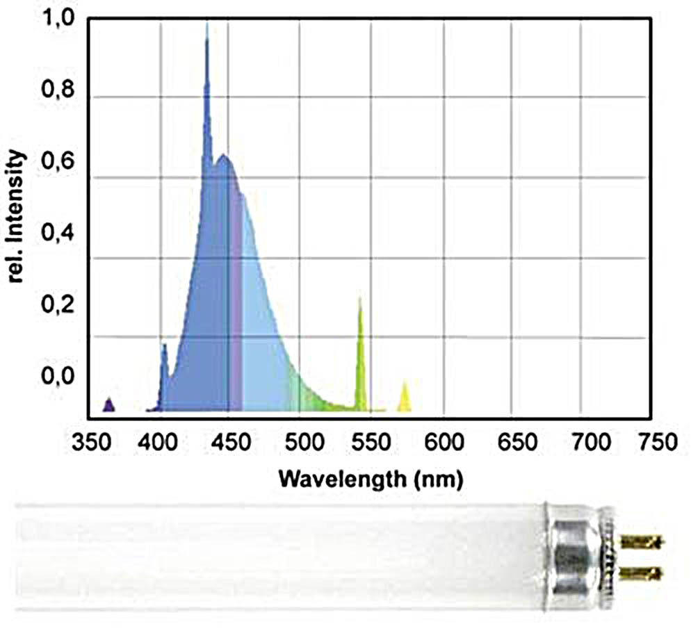
Fig. 10 A typical actinic fluorescent tube: Giesemann Actinic Plus
Let us consider the most popular actinic light sources for a reef tank. These are mostly fluorescent bulbs which mainly radiate in the 400-500nm range, such as Giesemann Actinic Plus, Fig. 10:
Looking at the spectral distribution of this bulb we can see that apart from the pure actinic spectrum, which is required for coral fluorescence, there are also distinct “parasitic” peaks around 550nm. As we have pointed out, the human eye is over 20 times more sensitive to the wavelengths in this range rather than to the “actinic” range which causes fluorescence (see Fig. 6).
As a result, this bulb is visually perceived as quite bright, almost white, but with strong blue-violet tint. The resulting fluorescence will be partially “dimmed” as a result of this parasitic radiation in the well-to-see range.
In recent years multiple attempts were made to create narrow-range “actinic” bulbs. One of the best is Giesemann POWERCHROME actinic plus, with significantly reduced 450-500nm portion (Fig. 11):
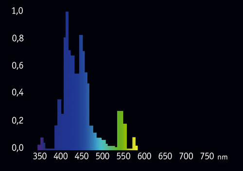
Fig. 11 The spectrum of the POWERCHROME actinic plus bulb
We can see that “parasitic” portion of this bulb’s spectrum is smaller and the 420-430nm range is better represented. However, this bulb too, still looks quite bright to the eye, because of the still present peak at 550nm. So far, conventional fluorescent tubes are not so efficient for observation of fluorescence in a reef tank.
Desperate? No! Quite recently, there was a breakthrough in the field of solid-state lighting, and many light fixtures for reef tanks are now constructed with the use of LEDs. The advantages of LED fixtures over the conventional light sources are many; we shall only consider the main factors.
Advantage #1: Higher efficiency and less heat generation
Higher efficiency has two components. First is that LEDs are about twice more efficient than conventional fluorescent tubes or Metal Halide bulbs in converting the electric energy into light. Second is that LEDs only radiate in one direction of the plane and hence are not apt to block their own light. By utilizing proper lenses, LED light can be easily concentrated in the desired region. Good LED lenses are compact in size and, at the same time, can help to transfer up to 90 percent of produced light through the water surface. For comparison, when using conventional bulbs with reflectors usually only 40% of light penetrates the surface. Best reflectors (often cumbersome) can yield up to 60% of light penetration, and the bulb itself partially blocks the light returning from the reflector. Resultant efficiency of best LED fixtures can be three times higher compared with the best light bulbs. Consequently, LEDs can generate over 4.5 times less heat. This practically means that by installing a LED fixture over a reef tank we can probably eliminate the need for an expensive chiller (which also consumes significant power). Thus, LED fixtures may achieve significant power savings; apart from the economic effect, their environmental impact is also significant!).
Advantage #2: Extended life cycle
As a solid-state light source, a light emitting diode does not have quickly wearing parts, such as an incandescent filament. When operated at or below rated current, and providing that they do not overheat, high quality LEDs degrade very slowly. But LEDs too have their specific needs which have to be considered when designing a fixture.
Lifespan of the best LEDs available in the market today (Cree XT-E, LUXEON Rebel ES) is indeed very high, if sufficient heat removal and properly conditioned power are provided. Of course, these are new LEDs and their operation have been tested for tens of years, but using complex models their life term and luminosity drop in that period can be estimated. We shall refer to two types of such forecasts: based on Cree’s model (which we call the “worst case scenario” or “pessimistic model”), and in parenthesis we provide figures based on the Philips model for their LUXEON Rebel ES (which we call the “optimistic model”). If all the required operation conditions are fulfilled, we will still be getting about 70% of LED’s initial radiation power after 40 (150) thousand hours of operation. These figures translate to 10 (33) years of operation of a light fixture, providing 12 hours of operation daily! After this period the LEDs will continue to lose luminance, reaching about 50% of the initial value after 100 (200) thousand hours!
The probability of a single LED failure on a fixture is quite low, about 1% during the period of 50 thousand hours of operation, and after this period the probability increases to 50% by 200 thousand hours. Several LEDs in a light fixture are usually connected in series, and therefore, if one LED dies, the whole string will be effected. If we look at these figures statistically, is likely that for a fixture with about 200 LEDs this can happen in 10 years. However a LED’s death is a probabilistic event and it can happen that a particular light emitting diode may get “fried” during the very first hours of its life. In practice, if the conditions are good, lifespan of modern LEDs is quite long.
In comparison, conventional fluorescent tubes need to be replaced once every four to six months. Based on our worst case scenario, it means that they will have to be replaced at least 20 times during the lifetime of a LED fixture. Providing that the cost of specialized tubes for reef lighting can be quite high, a LED fixture can provide significant savings; e.g., not only monetary, but also of the time that was to be spent for acquisition and replacement of light bulbs.
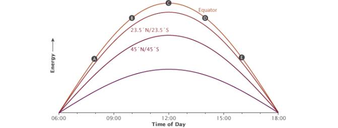
Fig. 12 The illustration shows how the time of day (A-E) affects the angle of incoming sunlight. Image courtesy of NASA Earth Observatory
Let us try to calculate the possible savings from using a LED fixture. A 300W LED fixture can replace a 900W T5 fixture used on a 160 gallon SPS reef tank. In 10 years the LED fixture will save ((900 300)/1000)*12*365*10 =26280KWh of electric power. The cost of electricity depends on where you live, how much you use, and possibly when you use it and the rates from the same provider can range from 12c to 50c per kWh [17]. For our estimate we shall use a sample rate of 15c per kWh, which is a reasonable example (you can find out how much you are actually paying for electric power by looking at your bill). Based on the 15c per KWH example, the fixture will save you $3942 in power alone. If we take the average cost of a specialized 80W T5 bulb to be around $25, we shall additionally save $25*10*20=$5000 in bulb replacements. Your total savings in 10 years will be about $8942. This is a “best scenario” estimate and we did not consider many additional expenses – for example, the cost of an aquarium chiller to remove the excessive heat from the tanks, as well as energy costs related to its operation. Besides, there are non-monetary values – such as the comfort of not having to provide maintenance on a light fixture in 10 years! Thus far, direct savings during the operational period are quite a few times higher than the cost of even most expensive LED fixture. In other words, not only you are getting it free, but it will even bring you some profit in its lifetime!
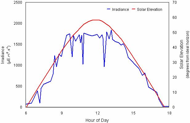
Fig. 13 Irradiance and solar elevation for September 2, 1998 at One Tree Island, Great Barrier Reef (23°30’S, 152°06’E) (Image courtesy of A. Salih, unpublished data)
Advantage #3: Ability to adjust illumination and spectrum
When using dimmable drivers, the light emitted by LEDs can be easily adjusted. Aquarists often use special controllers to imitate sunrises and sunsets, similar to natural illumination changes during the day. It is important to note, however, that sunsets and sunrises in the equatorial zone are much quicker compared with higher latitudes, and daytime is equal to night (i.e. there is always a 12 hour photoperiod). Look at the diagram shown in Fig. 12 [20].
Real irradiance at the surface depends on multiple factors, such as cloudiness, the amount of water vapors in the air, atmospheric turbulence, etc. The insolation measured at the Great Barrier Reef on a typical day is shown in Fig. 13[21].
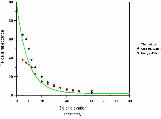
Fig. 14 Reflectance of sunlight in relation to solar radiation. Theoretical and measured percentage of sunlight reflected off a completely smooth water surface in relation to solar elevation (based on calculations of Weinberg, 1976; Grichenko in Weinberg, 1976)
Also note that the light is almost fully reflected when the sun rays touch the water surface at small angles. Reflection also depends on the wind speed. These dependences are illustrated by the diagram in Fig. 14 [21].
This means that natural illumination under water is not sufficient for photosynthesis until the sun rises approximately 15 degrees over the horizon. In approximately 30 minutes after this the illumination quickly increases to about half of the daily maximum value. Therefore actual photoperiod is about 9 hours. These are the factors an aquarist should consider if he is wishing to replicate natural light cycles.
Now let us consider important characteristics of light, which are required for our further conclusions.
First such characteristic is CCT – Correlated Color Temperature. CCT of a given light source characterizes the temperature of an absolutely black body that would radiate a similar spectrum. The hotter the black body, the higher will be the CCT and the more blue or “cold” will be the light. As an illustration, sunlight has a yellow tint, whereas blue giants – huge stars with high temperature of the surface: 10000K and above (Sirius, for example) – seem bluish even to the naked eye.
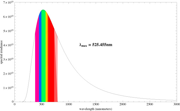
Fig. 15 The spectrum of a light source with CCT 5500K
Let us compare the radiation spectrums from two different absolute black bodies with different CCTs [10]. The diagrams also indicate the dominating wavelength. Fig. 15 pictures the spectrum of a light source with 5500K CCT, and Fig. 16 – with 6500K CCT:
You can see that the dominating wavelength increases with the increase of CCT: it is equal to 444nm for the relatively warm light of the 6500K CCT. For a 8000K CCT bulb the calculated wavelength is about 420nm. Practically speaking, CCTs over 20000K is senseless. However, light bulb manufacturers often “abridge” the spectrum to a particular range of special interest, offering light bulbs with the spectrum similar to the one shown in Fig. 17.
Even though the dominating wavelength of this bulb is about 450nm, it has a CCT of 25000K! [11]
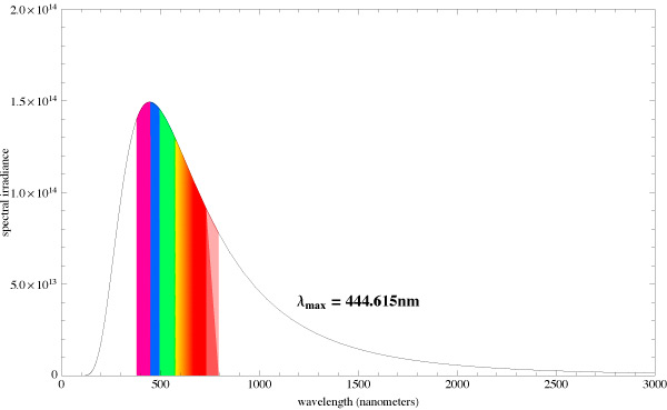
Fig. 16 The spectrum of a light source with 6500K
Thus, CCTs cannot be used as a criterion for the comparison of particular light source spectra. Moreover, even high CCT values do not guarantee that we shall get the required “actinic” spectrum.
Another important characteristic is CRI – the Color Rendition Index. Unfortunately this term is often interpreted wrongly. It characterizes the influence of light source on the perception of an object’s color. This parameter shows how correctly a light source with a particular CCT will deliver the color of an illuminated object, compared with an ideal source – an absolutely black body with the same color temperature. To determine the CRI, a set of 8 standard color samples is illuminated with the source and with the light of a back body with the same color temperature. If none of the samples change their color, CRI is equal to 100. The index reduces in inverse proportion to the number of color changes in samples. It is usually believed that a CRI above 80 is good. It is important to know, however, that CRI is calculated for light sources with a particular color temperature. It is not appropriate to compare a 2700K, 82 CRI light source with a 5000K, 85 CRI source.
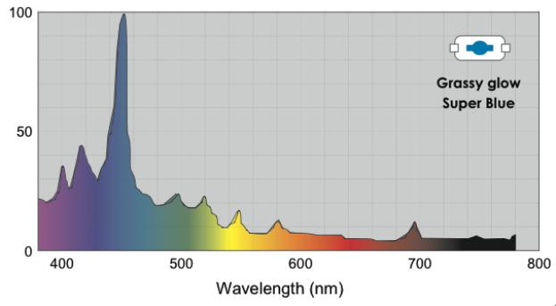
Fig. 17 The spectrum of the Grassy glow super blue 25000K bulb
Also note that CCT and CRI are only defined for full-spectrum light sources. The CRI of monochromatic light is close to zero, and its CCT cannot be calculated. Look at Fig. 15, Fig. 16 – you can see a wide spectrum, starting near 120nm and finishing around 3000nm. In this whole range a clear maximum is present, and most of energy is radiated in a narrow band of wavelengths. Radiation spectrum of a black body can never have the shape of a narrow-band spike, similar to the spectrum of a monochromatic light source, and therefore, calculation of CCT for such sources makes no sense.
All fluorescent and MH bulbs have a discrete spectrum, whereas sunlight has a continuous spectrum. Discrete spectrum is a result of using a discharge in mercury (and other metal) vapors, with several peaks at different wavelengths, mostly in the ultraviolet range. Phosphors on the bulb convert this radiation into narrow bands of visible light. A discrete spectrum vs. continuous is shown in Fig. 18.
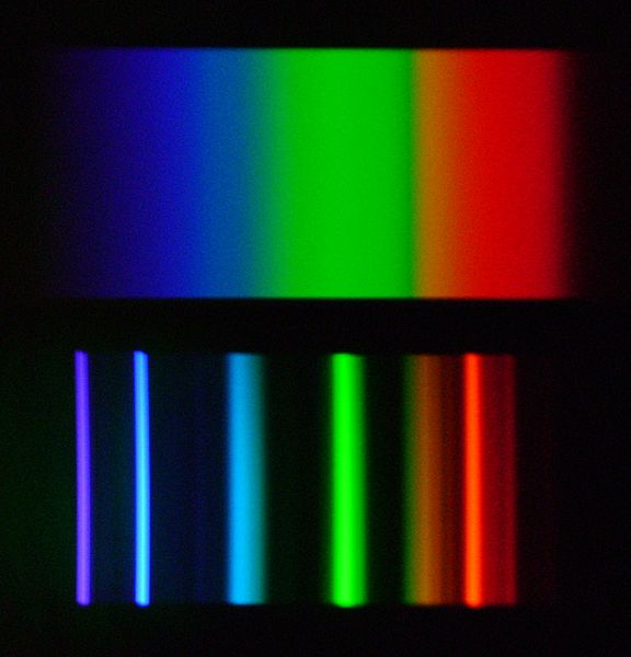
Fig. 18 Continuous (above) and discrete (below) spectrum
The gaps – wavelengths that are missing in a discrete spectrum – mean that certain tints of color cannot be correctly rendered under such illumination and, as a result, the light source will have a low color rendition index (CRI). Of course, light bulb manufacturers try to avoid deep gaps in the spectrum. Look at the spectrums of popular marine MH bulbs: BLV HIT 10000K and BLV HIT 14000K (Fig. 19).
These bulbs do not have deep gaps in their spectrum, so that the intensity at a certain wavelength would drop to zero, hence both are full-spectrum bulbs and their CRI can be determined. At the same time, they exhibit clear discrete peaks, meaning that when using these bulbs precise color rendition cannot be achieved. Note that bulbs with different CCT: 10,000 Kelvin – 14,000 Kelvin are used in this example. Their main difference is in the significant portion of 400-440nm radiation in the second bulb, whereas the 460nm peak is missing. This is logical and clear: the higher the temperature of an absolutely black body, the more its spectrum would shift into the short wavelength region. Since the 400-450nm range is most important for a reef aquarium, and because, in order to attract the customer, manufacturers often calculate the CCT to satisfy their interests, we can safely state that maximum radiation in the required range is only achieved when a CCT of approximately 20000K is declared. Have a look at the spectrum of a 400W Hamilton Metal Halide bulb with 20000K CCT (Fig. 20):
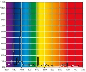
Fig. 19 The spectrum of Metal Halide bulbs BLV HIT 10000K (a).
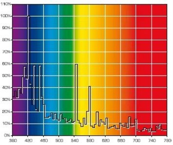
Fig. 19 The spectrum of Metal Halide bulbs BLV HIT 14000K (b).
This bulb radiates a significant portion of its power in the 400-450nm range, with a noticeable peak around 420-430nm. Only a small portion of radiated power in the longer wavelength range makes its light visible, rather than dark to the eye as violet-blue.
High CCT bulbs are often characterized by a significant portion of radiation in the 420-430nm range. Experienced reef aquarists recommend 20000K bulbs for providing the best color for marine organisms. This advice, obtained through years of practice, matches well with the conclusions we derived above.
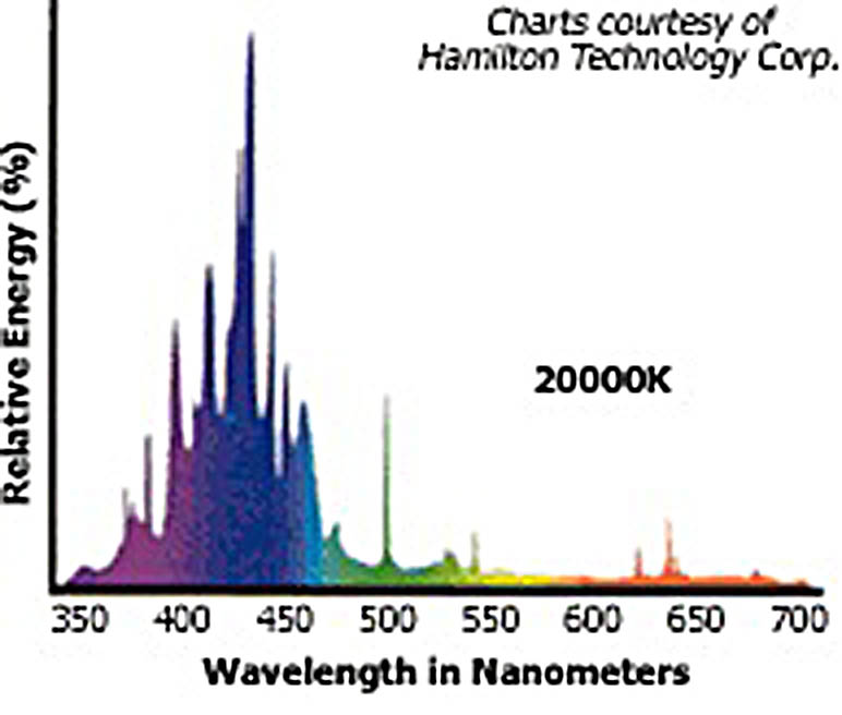
Fig. 20 The spectrum of a 400W Hamilton Radium Metal Halide bulb with 20000K CCT
Of course, there is an exception from any rule. In our case, such an exception is marine organisms which only live in shallow waters in their natural habitat, in the tidal zone for example. This is an important reservation: there are species which can live both in shallow waters and at medium depth, and they are quite tolerant of the light spectrum. Certain species, however, can only live close to the surface, and cannot survive even at small depths. Such species do not adapt well, not only to the weaker illumination but also to a different spectrum. Certain species of colonial polyps of the Zoantidae genus are an example of this.
Let us now consider the spectrum radiated by various LEDs. The spectrum of a cool-white LED with CCT around 7000K is shown in Fig. 21.
This spectrum is not discrete, but has a significant sag in the 470-500nm range. This gap can be compensated easily by adding a blue LED to the fixture. Have a look at the spectral power distribution for different color LEDs of Philips LUXEON Rebel ES series (Fig. 22).
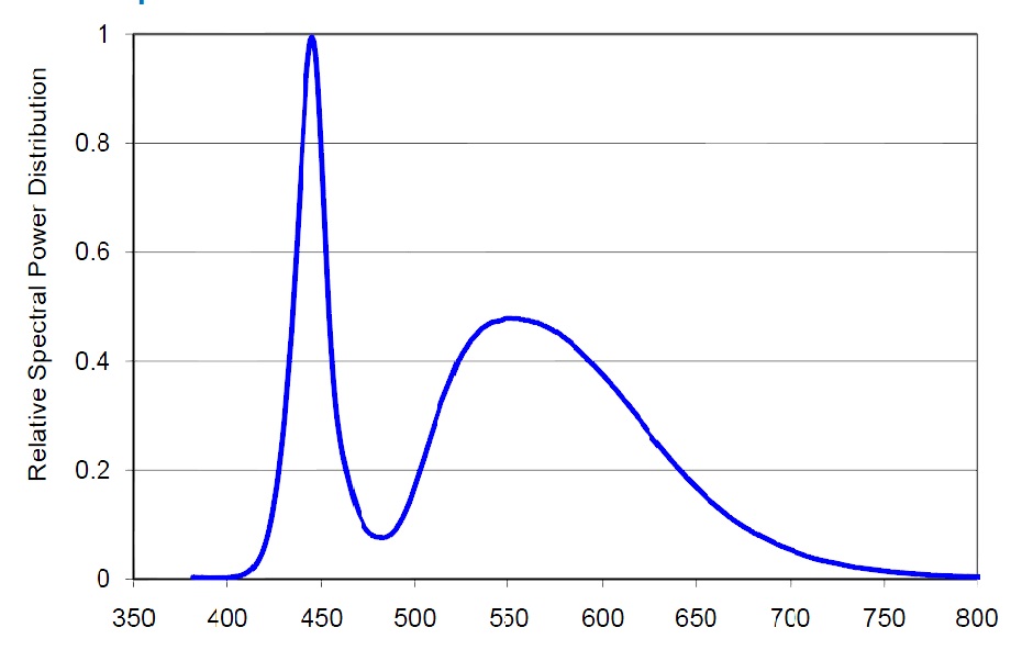
Fig. 21 The spectrum of a white LED
Radiation of the Blue LED is most suitable to compensate for the required 470-490nm range. Even a better match could be achieved by using a LED with a 475nm peak – fortunately, such LEDs exist!
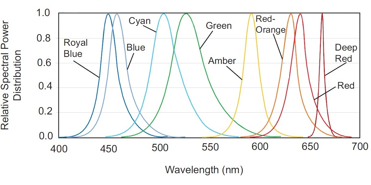
Fig. 22 Spectral power distribution of Philips LUXEON Rebel ES color LEDs
To better explain this, let us consider the term bin, which manufacturers use to characterize their LEDs. A bin is a group of LEDs that have been selected according to a certain parameter. There are efficiency bins, CCT and CRI bins, and dominating wavelength (DWL) bins are available for monochromatic (single color) LEDs. DWL bins for blue LUXEON Rebel color LEDs are shown in Table 1.
Adding a LED with the DWL bin code 4, we can flatten the white LED’s spectral curve in the 430 to 600nm wavelength range.
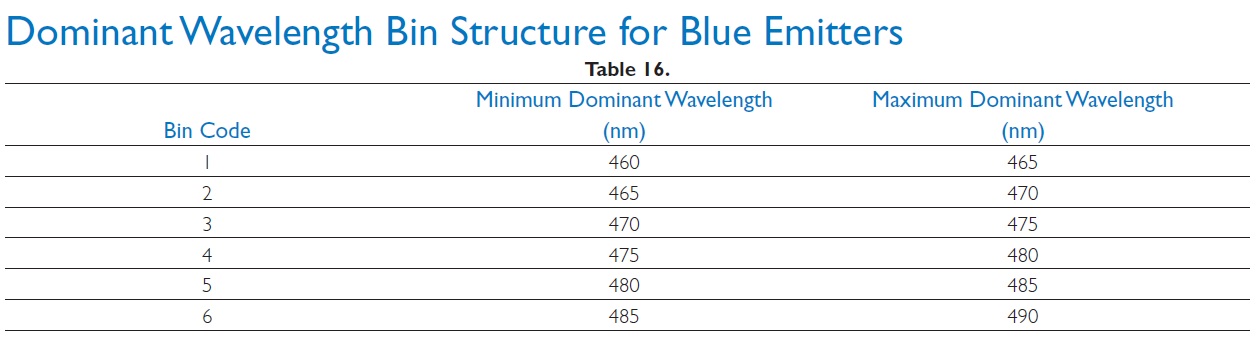
Table 1 LUXEON LED bin distribution by wavelength
We shall now turn to actual implementation of LED fixtures for the reef aquaria.
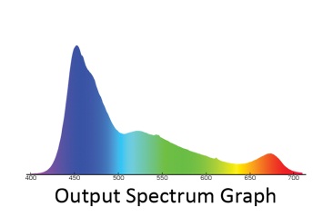
Fig. 23 Output spectrum graph of Ecotechmarine Radion LED fixture
Using just two types of LEDs (white and blue) is not sufficient, because such a fixture will miss a significant amount of light in the 400-450nm range – much less than it is measured in the ocean, at the depth of just a few meters. The 450nm spectral range can be easily scaled up by using Royal Blue LEDs with a corresponding peak. Apart from that, the white LED spectrum quickly diminishes in the dark-red range, around 650-660nm. According to the model shown in Fig. 4, this part of the spectrum is also required for shallow-water photosynthetic organisms and adding this range can be beneficial -it will also help to emphasize the red color in the reef tank. What kind of spectrum shall we attain as a result? Answer: Something very close to the spectrum of the best light fixtures that are commercially available today. As an illustration, Fig. 23 shows the spectrum of Ecotechmarine radion, ReefBuilders 2011 LED showdown winner [18].
As you can see, the gap in the 480nm range is properly filled (this fixture uses Cree’s blue LEDs). Besides, a small peak in the 660nm range is available. However, any wavelengths in the 400-430nm range, which could promote the fluorescence of many marine organisms, are virtually missing.
This range is missing in the majority of reef LED fixtures. Until recently, no LEDs of proper quality were available in the market for the 420nm range. For the few available offerings the prices were quite high, along with short operation time and poor efficiency. At the same time, the required total radiation in this wavelength range is quite significant, and adding the appropriate number of LEDs seriously affected the total cost of the fixture. As a result, manufacturers installed a tiny fraction of the required number of pure actinic LEDs, at best. In the beginning of 2012 this situation has the potential to change quickly since the introduction of efficient and relatively inexpensive 420nm LEDs [15]. By using these new generation LEDs in pure actinic wavelength range, it is possible to create an affordable LED fixture with proper spectrum required for the reef tank.
Many hobbyists tried to use inexpensive no-brand Chinese LEDs in the pure actinic range. However, their efficiency is low and, as a result, the crystal deteriorates quickly due to overheating. Worst of all, this deterioration is hard to estimate visually, since the eye’s sensitivity in 420nm range is very poor. Besides, spectral distribution of such low-quality LEDs can be very wide (from 350nm in the ultraviolet range, and up to green light): these longer wavelengths affect the visibility of coral fluorescence. At the same time the research conducted by the European Commission Joint Research Center [12] shows that UV light with shorter wavelengths may cause unsightly phosphorescence of small particles suspended in water (Fig. 24).
Fig. 24 Phosphorescence of small particles in water under UV illumination
The diagram contains several graphs for the phosphorescence of differently sized particles. We are mostly interested in particles sized around 60 μm, which are abundant in a reef tank. When irradiated with wavelengths shorter than 370-380nm, this phosphorescence can be quite significant.
Wide spectral diagrams of previous generation LEDs contained a significant portion of 370nm radiation which caused noticeable phosphorescence of suspended particles in the aquarium, hence many DIY LED fixture builders recommended the use very few pure actinic LEDs.
Fortunately, the newest generation of LEDs has an efficient bandwidth of about 30nm [15], and by using LEDs in the 400-430nm range we can avoid the phosphorescence of suspended particles, even though total radiation power can be quite high.
We shall now try to estimate the amounts of light at selected wavelength ranges: 400-440nm, 440-480nm, 480-520nm, and 520-700nm. Each range will correspond to one color channel in a LED fixture and can be achieved by using one type or a combination of several types of LEDs.
Insolation at the ocean surface depends on the presence of clouds, position of the sun, and other factors. For our estimates we shall assume an average monthly insolation of 1789 J/cm2, based on 3 months statistics for Fiji [20]. Assuming a 12 hours photoperiod, this translates to 413 W/m2.
By integration of solar radiation power in accordance with Fig.3, we shall obtain the distribution of visible light power in the above sub-ranges for different depths (Table 2):
Table 2 Average light power (in W per sq.m.) for the defined spectral ranges during the day
| Spectral sub-ranges, nm | |||||
|---|---|---|---|---|---|
| Depth, m (feet). | 400-440 | 440-480 | 480-520 | 520-700 | Total power |
| 0 (0) | 55 | 64 | 62 | 232 | 413 |
| 5 (16.4) | 54 | 63 | 60 | 163 | 340 |
| 10 (32.8) | 53 | 61 | 57 | 94 | 266 |
| 15 (49.2) | 52 | 60 | 55 | 26 | 193 |
Although the table is based on naturally available spectral distribution at specified depths, note that the 400-500nm range is the most required, since it provides the best coloration and fluorescence in corals; whereas, the longer wavelength radiation in 500-700nm range is poorly utilized by marine photosynthetic organisms. At the same time, the human eye is very sensitive to the 520-600nm range and therefore we do not need very much radiation power in that range: even small amounts of illumination will be sufficient for the eye to perceive the tank as brightly lit. Meanwhile, supplementation of 660nm LEDs can be beneficial for shallow-water organisms. At the same time, this wavelength, in combination with the 400-420nm range, will promote correct rendition of the purple color.
As we have shown, the 400-480nm range is most important for marine photosynthetic organisms. In their natural environment corals are getting 52 to 55W/m2 of optical power in the 400-440nm range and 60 to 64W/m2 in the 440-480nm range.
If only these wavelengths are used in the fixture, using the empirical expression Watts/m2 = 0.21*L [19], we can achieve illumination levels between 528 and 567 μmol·photons/m2/s. As it was shown above, this is sufficient for proper growth and coloration of light-demanding corals.
However, we do not recommend using that much radiation power all the time over the reef tank, and the following factors should be considered:
- Apart from the mentioned wavelength ranges, for an improved visual effect most hobbyists will also utilize LEDs in other ranges. These LEDs will also contribute to total radiated optical power.
- Radiation power over 400μmol·photons/m2/s can be too high. Production of chromoproteins stops below 100 μmol·photons/m2/s; i.e., at an illumination level 4 times smaller.
- Many aquarists are using controllers to imitate sunrises/sunsets and other effects, and radiated power may change significantly during the day. Mean power during the photoperiod is less than the maximum power.
- Marine photosynthetic organisms most efficiently utilize radiation with the wavelengths around 430nm, and this range also stimulates their most intensive coloration.
We believe that the most reasonable maximum radiation power should be about 45W/m2 for the 400-440nm range and about 40W/m2 for the 440-480nm range. Note: Here and above we mention optical radiation power rather than the electrical power consumed by the LEDs. To determine the number of LEDs required in a fixture and their rated current these figures must be converted into electrical power, which depends on the efficiency of the LEDs actually used. These calculations, selection of particular LEDs and other matters concerning the actual construction of a LED fixture will be considered in our next article.
If the reef tank is only illuminated in these wavelength ranges for 12 hours, with short sunrises and sunsets specific to the equatorial zone, we will obtain an average radiation power of 400μmol·photons/m2/s, which is sufficient for optimal production of chromoproteins. Since the light fixture is likely to also include LEDs in other wavelength ranges, we can safely assume that these figures include some power margin.
Also note that although 400μmol·photons/m2/s radiation power is optimal for coloration of corals, such high illumination requires pristine water conditions in the tank. Radiation power 4 times below this level is already sufficient to start production of chromoproteins in corals. We recommend starting slowly, with initial lighting levels close to the lower boundary of about 100μmol·photons/m2/s. Within several months you can gradually increase the illumination, while closely monitoring water parameters and the corals’ reaction. If the system is stable and all parameters are in the optimal range, optical power can be gradually increased up to 400μmol·photons/m2/s.
As we have seen, formal parameters such as CRI and CCT are not very useful for determining whether a particular light fixture is suitable for a reef tank. At the same time we need to point out again that sufficient power in the 400-480nm wavelength range is critically important. If this condition is fulfilled, other parameters of the light fixture may be selected based on the owner’s individual preferences (just make sure that the total radiated power does not exceed the recommended values). We have to admit, unfortunately, that most of the commercially available light fixtures today are only utilizing the 450nm range and above, whereas an ultimately important range between 400 and 440nm is usually left out, or is inadequately represented.
References
- http://en.wikipedia.org/wiki/Color_vision
- David H.Hubel, Eye, Brain and Vision. 256p., 1995, ISBN/ASIN: 0716760096
- http://www.ecse.rpi.edu/~schubert/Light-Emitting-Diodes-dot-org/Sample-Chapter.pdf
- http://ies.jrc.ec.europa.eu/uploads/fileadmin/Documentation/Reports/Global_Vegetation_Monitoring/EUR_2006-2007/EUR_22217_EN.pdf
- http://rybafish.umclidet.com/zooksantella-%E2%80%93-nevolnica-korallov.htm
- http://afonin-59-bio.narod.ru/4_evolution/4_evolution_self/es_13_algy.htm
- http://medbiol.ru/medbiol/botanica/000a984c.htm
- http://batrachos.com/node/442
- http://reefcentral.com/forums/showpost.php?p=20296037&postcount=27
- http://www.photo-mark.com/notes/2010/nov/19/plancks-despair/
- http://reefbuilders.com/2010/06/17/grassy-glow-25000-k-metal-halide-bulb-from-volx-japan-hits-the-mark-for-blue-light-addicts/
- http://ies.jrc.ec.europa.eu/uploads/fileadmin/Documentation/Reports/Global_Vegetation_Monitoring/EUR_2006-2007/EUR_22217_EN.pdf – 26p.
- R.W.Burnham, R.M.Hanes, C.J.Bartleson Color: A Guide to Basic Facts and Concepts. New York: John Wiley, 1953
- Thai K. Van, William T Haller, and George Bowes Comparison of the Photosyntetic Characteristics of Three Submersed Aquatic Plants. www.plantphysiol.org/content/58/6/761.abstract
- http://www.led-professional.com/products/leds_led_modules/semileds-achieves-40-external-quantum-efficiency-for-ultraviolet-uv-led-chips
- C.D’Angelo, J.Wiedenmann, Blue light and its importance for the colors of stony corals, Coral Magazine, Nov./Dec. 2011
- How much electricity costs, and how they charge you
- Ecotech Marine’s Radion XR30w wins the 2011 Reef Builders LED showdown
- http://www.onsetcomp.com/support/knowledgebase/unit-conversion
- http://earthobservatory.nasa.gov/Features/EnergyBalance/page2.php
- http://reefkeeping.com/issues/2002-09/atj/feature/index.php
- Leletkin V.A., Popova L.I., Light absorption by carotenoid peridinin in zooxanthellae cell and setting down of hermatypic coral to depth, Zh. Obshch. Biol. 2005 May-Jun;66 (3)
best article on reef light by far