

In our previous article we considered theoretical aspects of reef lighting, such as the light spectrum and intensity required for growing corals and achieving their best coloration. We would now like to discuss the various practical challenges one faces when designing a LED light for the reef tank.
Over one year has passed since the publication of our first publication on reef lighting. We planned to publish our second article on practical aspects of building a LED fixture shortly thereafter. At the time, we were actively working on the design of a special LED assembly that, based on our understanding of reef lighting requirements, would be best suited for a reef keeper’s needs. However, we decided to postpone the publication, until our ideas fully matured based on our actual achievements.
As our work progressed, we decided to share not only theoretical stipulations, which were our starting point, but also the experience we gained through the efforts towards creating a light source that would not only provide for good coral growth but would also yield premium results in the visual perception of a reef tank.
The first part of this article describes how we planned our LED assembly; in the second part we describe our progress, in several successions, towards the latest version of our product.
We hope that our practical achievements, the problems we encountered, and our attempts at solving them will prove useful to the reef keeping community.
Contents
- Part One: Planning
- Part Two: Our Attempts at Building an Optimal LED Assembly
- Light diffusers
- Acknowledgements
- References
Part One: Planning
When planning for a light source for a reef tank, there are many aspects that we needed to take into account. One challenge is the choice of LEDs that would provide for optimum efficiency. The next challenge is achieving uniform color mixing, in order to avoid unsightly color shades (“Disco” effect) in the tank. Another challenge is how to organize efficient heat removal from the LEDs. Last but not least, we need to “fill up” the spectrum, i.e. which supplemental colored LEDs to use for best visual representation of the corals. We shall consider these challenges in detail in the subsequent sections.
Choice of LEDs
It is evident that, whenever possible, preference should be given to LEDs manufactured by one of world’s leading manufacturers: either Cree or Philips – they provide the best efficiency among commercially available LEDs today.
The specifications of many reef LED fixtures available today list the brands and types of LEDs used (such as Cree XT-E or Philips Luxeon Rebel). Yet, most manufacturers do not specify, the particular LED bins which they used in their fixture. Still, bins are a very important characteristic which we need to keep in mind when building a LED fixture.
What is a bin? Due to technological reasons, the parameters of LEDs can be different even within the same batch. To achieve a product with uniform quality, leading LED makers sort out their product into several categories, depending on certain characteristics, which they call bins. Color bins contain LEDs with similar wavelengths, or spectrum; luminosity; whereas, efficiency bins consist of LEDs that are sorted out according to the efficiency of converting the electric energy into light. Each manufacturer assigns certain bin codes to these LEDs, and this bin code is attached to LED model number in order to better characterize the properties of the lot that is offered for sale.
If we look at the offered color bins, for example, we can see that emitters with different prevailing wavelengths are available for the same LED type. For example, consider the newest generation of Philips Luxeon Rebel ES Royal Blue emitters (Fig 1):
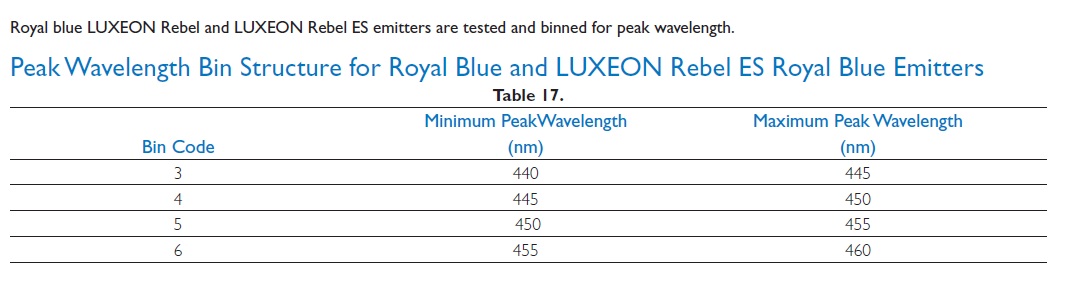
Fig 1 Peak wavelength bin structure for Luxeon Rebel ES Royal Blue emitters
The ability of the human eye to differentiate between close shades of color depends on the range. It varies from approximately 1 nm resolution in the blue-green and yellow wavelength ranges to about 10 nm or poorer for red and blue [1].
It is easy to see that by looking at the bin code. LED emitter’s peak wavelength can vary significantly. Color bins can be very narrow, sometimes only 5nm wide or even less, and it is important to take this into consideration when we want the whole desired spectral range covered – otherwise we can miss some shades of color in our fixture’s light.
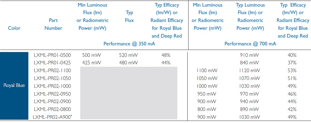
Fig 2 Radiometric power of Luxeon Rebel ES Royal Blue emitters at 350 and 700ma, depending on luminosity bins
The second binning category – luminosity or efficiency bins – is also very important. The manufacturers use this bin type to sort out their LEDs according to the optical power output, while the electric power consumption is the same. Even for the same LED type the difference in efficiency between bins may be significant. Let us have another look at the datasheet of same Luxeon Rebel ES Royal Blue (Fig 2).
You can see that the efficiency of electric power conversion into light energy can vary from 37% to 53% for different bins at the same current. This means that the best bin is some 40% more efficient compared the worst bin!
Thus, by installing less efficient LEDs in a “cheapo” fixture, it will yield 40% less light compared with the use of best bin LEDs. Yet, at a glance (and even according to fixture specification – if bins are not mentioned), both will seem to be utilizing the same LEDs.
Of course, fixture manufacturers are tempted to use less efficient LEDs, since the best bin’s price can be twice as much as that of the worst bin (besides, LEDs of topmost quality are scarce; they are usually not readily available for purchase and “catching” the best bin requires significant efforts from the fixture manufacturer).
This concerns the LEDs of same type. Price (and efficiency) difference between different LED generations is way higher. Therefore, beware if a manufacturer only specifies that “the fixture is made with Cree LEDs.” without even specifying the particular LED type used – it is most probable that the fixture may be using LEDs which are two or even three generations old, which offer mediocre performance, at best.
Unfortunately, manufacturer’s interests do not always match that of the user. The cost of LED emitters is only about 20% of the total fixture cost, but this additional 20% expense can provide up to 40% extra light, and add an additional advantage, less heat generation and power consumption. If we consider a 300W LED fixture as an example, calculating for 12H daily operation, and based on a 15c per kWh power cost, the total power consumed in 10 years of operation will cost (300/1000*12*365*10*0,15)=$1,971 for a fixture with the worst bin, while the owner of a fixture with the best bin would save $788 throughout this period.
There are many other advantages in using LEDs with better efficiency, which are far more difficult to account for objectively due to many unknown variable factors. To name a few, less efficient LEDs will result in higher junction temperature during operation, which in turn, will further reduce their light performance and result in a shorter lifespan of the LEDs. The heat from a less efficient fixture will be transferred to the environment, and it is more likely that the tank and the room will require a more powerful cooling unit.
So far, our estimates were based on a 40% efficiency difference between the best and worst LED bins of the same type. Depending on the LED type, this difference can be higher or lower. If we extend our speculations and start to consider LEDs from different manufacturers, this efficiency difference can be much higher. If we compare low-cost Chinese LEDs, which now flood the market, with the best bins from the best manufacturers, there can easily be three a times efficiency difference, or even more!
In fact, this means that by choosing between two fixtures of same power but a three-times price difference, one may to yield less light per dollar from the cheaper fixture (this is true under the assumption that the fixture cost is directly linked with the cost of used materials rather than other marketing factors). At the same time, the less efficient fixture will spend much more in power bills in a fixture’s lifetime.
Worst of all, it is almost impossible to accurately measure LEDs efficiency at home, and manufacturers are tempted to indicate a higher efficiency for the LEDs they use: serious errors in LED fixture specifications are common.
We believe that the choice of most efficient LEDs is very important when building a fixture. As we have shown, their higher cost will be justified in time.
There are a few other important issues which are often poorly addressed in existing fixtures.
We have heard claims from many experienced reef keepers that LED lighting has not yet matured for aquarium use. We believe that this notion is caused by two main shortcomings of the existing fixtures: spectrum deficiency and poor color mixing which results in multicolored blotches and shades.
The first problem is relatively easy to address by combination of different LEDs in order to cover the desired spectrum fully (in our previous article we have shown that violet spectrum plays an important role but is neglected or poorly represented by most manufacturers, mainly due to the high cost).
The second problem requires a complex of efforts to achieve an acceptable solution. Some people spot these color blotches at once, while others may require time to notice the problem. Still, it is very important to eliminate this effect, as it affects our perception of the reef tank directly.
Challenge number one: Getting rid of color shadows (disco effect)
The so-called disco effect is witnessed when a tank is lighted by several power LEDs (especially multi-colored) which are positioned on a certain distance between each other. Each LED is a point light source, resembling a small sun. When illuminated by several LEDs from different directions, every object produces multiple shadows. When these LEDs are of different color, these shades look colored like disco lights.
The only way to overcome this effect is to place LED crystals as closely as possible. We cannot place all the LEDs of the fixture in one place, as we want to light up the whole surface more-or-less uniformly. Therefore, we need to gather all differently colored LEDs in groups, in the required proportion. These groups can then be evenly spread over tank’s surface.
One option is to collect a group of LED crystals in a small space by creating a custom COB (Chips On Board) with many LED crystals closely packed in one case. A COB is a matrix of individual LED crystals attached to a common platform and covered by a protective compound (usually silicone). They have several advantages over SMD LEDs and are becoming quite widespread for general lighting use. Indeed, they are easy to mount, provide a relatively low cost per emitted light, and are undemanding to optics – they are, indeed, very good when you need lots of light from an inexpensive fixture. COBs can be very good for the lighting of roads, warehouses, or other large premises.
Custom COBs can provide a perfect color mix if crystals with the right spectrum are selected. However we believe that COBs are not the best choice for a reef tank. Three factors are most important when building a reef fixture: spectrum, efficiency, and optics.
In theory, a COB may contain any crystals. However, none of the top ranking manufacturers, neither Cree nor Philips Luxeon, cover the whole spectral range required for reef lighting. Cree, for example, does not make violet (“true actinic”), or deep red LEDs, Philips Luxeon also doesn’t cover the violet range. Of course, there are smaller companies which make a wider range of LEDs, and their crystals cover the required spectrum. However, our second requirement – efficiency – would suffer. Theoretically, crystals from different manufacturers can be combined in one COB package, but this can be practically impossible for similar crystals, made by different brands. As a result, the COB will have to use crystals with significantly lower efficiency, compared with world’s leading manufacturers. Our calculations based on the datasheets from leading Taiwanese manufacturers – Epistar/Epileds, show that there can be as much as 54% difference in efficiency compared with best individual LEDs from top manufacturers. Besides, manufacturers usually don’t put their best crystals into COBs. Even Cree declares about 34% less efficiency for their best COBs today, compared with individual LEDs.
A shorter thermal path in COBs is usually listed as an advantage, however, this is not as simple as it seems. As an example, let us consider Cree’s newest COBs. As one of World’s top leaders in LED technologies, this company pays closest attention to improving the thermal characteristics of their products. According to the datasheets, thermal resistance of Cree’s COBs varies from 2.5°C/W for CXA1507 to an impressive 0.8°C/W for CXA2530. Seems to be pretty good, huh? Only until we notice that, say, CXA2520 may consume up to 50W of power. According to the datasheet (see the picture below), this will add a significant 40С to junction temperature above the temperature of the LED case. For CXA2530, with 61W power consumption, junction temperature will be even higher.
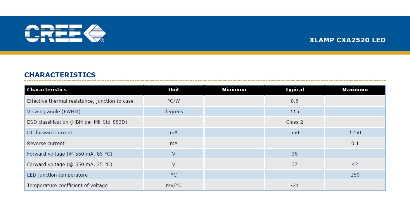
Fig 3 Main characteristics of Cree CXA2520
Note that the thermal resistance of COBs from Asian manufacturers is usually even higher than those of Cree. This can result in serious overheating of the crystal (even though the heatsink temperature may stay in the acceptable range).
A better approach would be, instead of COBs, to use carefully selected individual LED emitters (the ones with most efficient bins, to minimize heat generation), then mounted on an advanced MCPCB to provide the best heat dissipation from the crystal. This can yield less than a 10°C temperature difference between the junction and the MCPCB, and about 12°C between junction and heatsink (see our thermal vision study, Fig 9).
Therefore, we believe that the best approach to avoid the Disco effect is through the use of individual LEDs packed tightly on a custom MCPCB. This way the light beams from differently colored LEDs will mix up well, without forming color shadows. The smaller is the distance between individual LEDs, and the better it will be able to overcome the color shade effect.
The distance between individual LEDs, however, cannot be smaller than the size of secondary optics. Fortunately, compact and efficient LED lenses are available today. The best effect is achieved through the use of hybrid optics, combining a TIR lens and a special light diffusing material.
Challenge number two: Battling the heat
Modern LEDs are quite efficient at the conversion of electric energy into light. However, even the most efficient LEDs today waste about half of the consumed energy in the form of heat. Since the crystal is quite small (a power LED’s crystal usually has the surface of only 1-2mm2 or 0.0015-0.003in2), its generated heat density is quite large. In fact, it is about 30 times as large as the heat density through the soleplate of a household iron!
Heat removal from LEDs is very important since their lifespan and performance depend on the operating temperature. When the temperature of the crystal increases from 25 to 100C the performance of the most heat tolerant LEDs (Luxeon Rebel ES royal blue) decreases by 10%. In the same time, less heat tolerant LEDs may lose up to 75% of their efficiency (Luxeon Rebel amber). This drop of efficiency is even more pronounced in cheap LEDs of Asian make.
Unfortunately, commonly known technologies today do not permit mounting the LED crystal directly on the heatsink. The crystal requires a special package, and its heat transferring capability is described by a parameter called thermal resistance, usually measured in the degrees of temperature increase per watt of generated heat (C/W). The thermal resistance of the best individual LEDs is about 2.5C/W today.
Let us consider the influence of thermal resistance on crystal temperature. Suppose we have two 3W LEDs of the latest-generation. Let us consider, for example, a violet LED Semileds N35L-U-A with a thermal resistance of 4.4C/W, and a Cree XP-E2 green LED with 15C/W thermal resistance. When operating at 700mA, the respective voltage drop will be, approximately, 3.3V and 3.5V, and hence their overall power consumption will be around 2.31W and 2.45W respectively. In the first case, the LED package will add 2.31*4.4=10.16С to crystal temperature, and in the second case the temperature difference is much higher: 2.45*15=36.75С.
We need to supply current to the LED and the conductors should be somehow isolated from the heatsink. Therefore, the LED emitter is first installed onto a special PCB, which is then mounted on the heatsink. Thermal resistance of least expensive PCBs can be as high as 60C/W or more (see the datasheet for Cree XLamp _PCB_Thermal.pdf). This, however, is quite unacceptable, and therefore special metal PCBs (МСРСВs) have been developed. Their structure is shown in Fig 4:
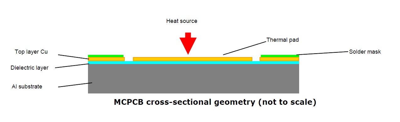
Fig 4 MCPCB cross-sectional geometry
You can see that the LED thermal pad does not touch the MCPCB metal directly, but through a thin dielectric layer. Unfortunately, thermal conductivity of dielectric materials is hundreds of times less than that of aluminum or copper, and МСРСВ’s total thermal resistance is somewhere between 0.2C/W (for LEDs with large surface area) and 5.3C/W for smaller crystals. Since we are planning to pack the LEDs tightly, in order to avoid the “Disco” effect, we shall assume a larger figure, towards 5C/W. This will add another 11.5С to 12.25С to the temperature of our crystals. These calculations are valid for a traditional MCPCB, but we can improve the situation significantly by using an advanced MCPCB like SinkPAD or similar.
The МСРСВ is not a part of the heatsink and is attached to it through a layer of heat conducting compound, which is required to fill in the gaps resulting from manufacturing imperfections of the attaching surfaces. The compound’s thermal resistance depends on material but, in any case, the thinner is the layer, the less will be the resistance. As a rough approximation, for a high-quality compound it is around 2C/W. This will add 4.6С and 5С respectively to our crystals.
Once the heat from the LED has reached the heatsink, it cannot be instantly transferred to the environment. A heatsink is usually selected in such a way that its average temperature would not exceed 50C when the surrounding air temperature is 25C. Heatsink temperature at the contact point with the МСРСВ will be around 60C. Thus, the crystals temperature will be 60+10.1+11.5+4.5=86.1С and 60+37.5+12.25+5=114.75С respectively. Note that if we attach such LEDs to a cheap FR-4 PCB with thermal resistance about 60C/W, crystal temperature may reach 252С. Since LEDs are attached with a solder which melts at about 217С, the LED would probably unsolder due to its own heat!
Note that our quoted 15C/W thermal resistance isn’t the worst case scenario: many Asian manufacturers avoid indicating this parameter in their datasheets, just because the figure is even worse. Also note that real-life temperatures will be worse than we calculated above, because of mounting imperfections of the МСРСВ, an uneven layer of the heat conductive compound, etc.
As we have seen, there are two main obstacles to removing excess heat from the LED crystal: the LED package and the MCPCB. Manufacturers are constantly working to overcome the first obstacle and the best LEDs on the market are using packages with reduced thermal resistance. Overcoming the second obstacle is more of a challenge since, until recently, there was no technology that would allow engineers to get rid of the dielectric layer between the LED thermal pad and the МСРСВ metal. In 2011, however, a US company SinkPAD (www.sinkpad.com) has offered a patented technology called SinkPADTM, allowing it to dissipate the heat from LEDs thermal pad directly to МСРСВ’s metal.
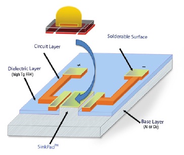
Fig 5 SinkPAD MCPCB structure
The structure of the SinkPAD МСРСВ is shown in Fig 5:
You can see the raised portions of the МСРСВ metal in the picture, which touch the LED’s thermal pad directly; whereas, the electric traces are situated on a separate PCB. This approach results in a significant reduction of thermal resistance, and the more LEDs there are on the MCPCB surface, the more pronounced is the effect. Therefore, this technology is preferred for our МСРСВ which will be densely populated with power LEDs.
Challenge number three: Filling up the spectrum
The MCPCB shall contain individual LEDs, or groups of LEDs, each radiating at different wavelength ranges. With this approach we shall be able to adjust the resulting spectrum as we find appropriate.
Below, we shall consider the general rules which we believe are important when designing a LED assembly, pointing out the problems and solutions that we had found in the process.
First of all we need to stress that, even for the same LED type, the efficiency may differ significantly, and all serious manufacturers sort out the product into several efficiency bins (which, inevitably, also differ by the price). We believe that only the best (most efficient) bins are suitable for making the LED assembly: the price margin will pay off several times throughout the many years of operation. At the same time, higher conversion efficiency means less heat generation, which is also a significant factor, especially within a LED fixture’s confined space. If not specified otherwise, we always use the most efficient LED bins that are available in commercial quantities at the time of manufacture. Some explanations are required regarding this commercial availability, however. In the datasheets LED manufacturers usually specify a list of bins, including some bins which they are not yet capable of manufacturing in sufficient numbers at the time the document is created. With time, the manufacturing process will be refined and a higher yield of higher quality LEDs will be achieved, but initially, the share of the best bins is very low and they aren’t offered for sale.
Spectral considerations
We have pointed out the importance of violet spectrum multiple times in our previous article. Beside the high photosynthetic activity, this spectrum provides strong fluorescence and, at the same time, it is very poorly visible to the human eye. We have also shown that, in natural sunlight, the amount of radiation in this part of the spectrum is significant. Therefore we install on our assembly several true violet LEDs with different wavelengths, covering the 400 to 430nm range. Spectral differences between these LEDs are hardly visible to the eye, and therefore we combine them all in one chain, without the possibility of individually controlling each sub-range.
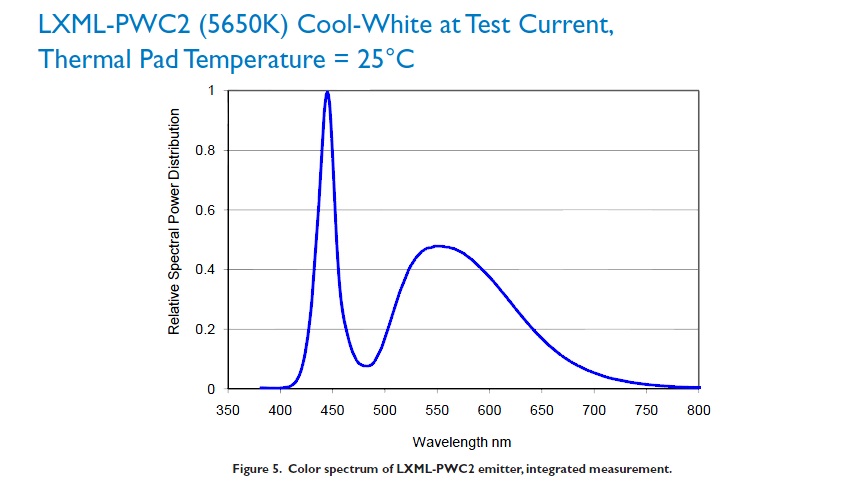
Fig 6a) Radiation spectrum of LXML-PWC2 (5650K) Cool-White emitter at Test Current, Thermal Pad Temperature = 25C
Unfortunately, high quality and efficient violet LEDs are still very expensive and in fact, if installed in sufficient quantity, they account for most part of the LED assembly’s overall cost.
The next important component of the assembly are white LEDs. The situation is much better here – white LEDs are manufactured in great quantities for general illumination needs. Usually they are based on royal blue LEDs with special phosphors applied on top, to convert some of the blue light into longer wavelengths. This technology is highly polished and is being perfected constantly. White LEDs are readily available for a moderate cost, even when the most efficient bins are requested.
Spectral distribution of light emitted by a cool-white emitter LXML-PWC2 (by Philips) is shown in Fig 6 (a), and a warm-white emitter LXW9-PW27 in Fig 6 (b) below:
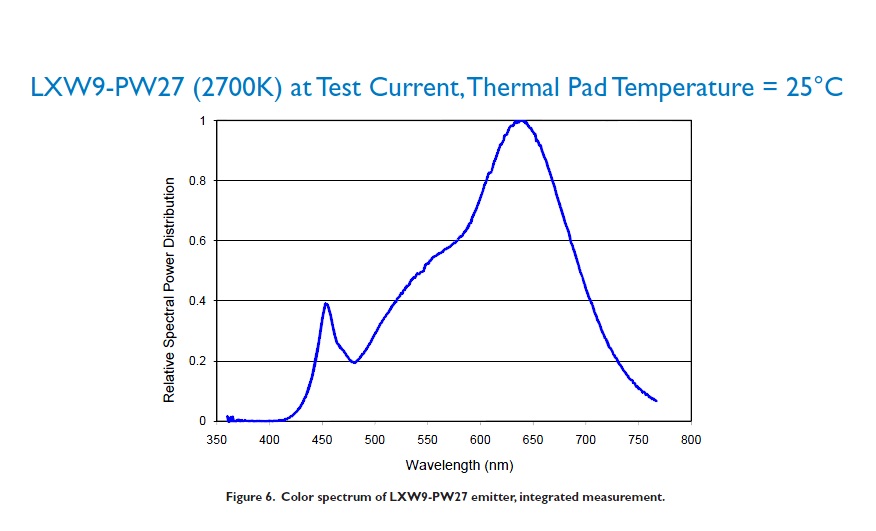
Fig 6b) Radiation spectrum of LXW9-PW27 (2700K) Warm-White emitter at Test Current, Thermal Pad Temperature = 25C
Note that in a cool-white emitter a larger portion of the blue light (about 440nm) emitted by the crystal penetrates through the phosphor, whereas a larger percentage of this light is converted to longer wavelengths in the warm-white emitter. The efficiency of this conversion is not particularly high, and therefore the efficiency of warm white LEDs is usually less compared with similar cool white LEDs.
We believe that cool-white LEDs with 6000-8000K CCT are best suited for the LED assembly to be used on a reef tank. A cooler white, if required, can be obtained easily by supplementing the radiation from blue and violet LEDs on the assembly. Using this approach, we can use the most efficient cool white LEDs on the assembly and, at the same time, will have an efficient tool for increasing the overall CCT when required.
Looking at the spectral plots of white LEDs, it is easy to notice a marked drop in the 475nm range. To achieve a more even spectral distribution in this range, a blue LED with corresponding wavelength shall be supplemented to the assembly.
The next color that is worth having, in order to better fill the gap in white LEDs spectrum, is cyan, or turquois, with wavelengths around 510nm. This is a rather bright bluish-green color and is visually quite pleasant.
Lately many manufacturers of LED fixtures have also been including green LEDs in their products. We believe that this is an unnecessary option. First of all, the true green spectrum, in the 530-560nm range, is already present in sufficient amounts in the spectrum of white LED, and therefore a separate green LED is not required on the assembly. Another disadvantage of using separate green LEDs is that so far the efficiency of commercially available green LEDs is extremely low and, to make their addition meaningful, a significant number would be required (even though the human eye is most sensitive to green spectrum), and this will affect negatively the overall heat generation by the assembly. We believe that adding just a few green LEDs to the assembly, like most manufacturers do, is a tribute to fashion and does not have any noticeable impact on the aggregated spectrum of the fixture.
Separate green LEDs in a fixture can only prove useful for a hobbyist willing to experiment with very unusual spectral combinations (like, for example, illuminating the tank with purely green light, or its combination with some other colors to achieve a certain design effect) and thus making a narrow-band adjustments across the whole spectrum. Anyway, such brave souls will require a completely different setup than your usual LED fixture, eliminating the white (and any other wide-spectrum LEDs) completely and substituting them with a multitude of different narrow-band LEDs. It needs no explanation that such unusual combinations can only be used for achieving short-term impressions and are not appropriate for general health and coloration of corals.
The orange and red spectrum is also required on the LED assembly, in order to emphasize corresponding shades of color in non-photosynthetic corals and fish.
Through our numerous experiments with LED lighting during the past year we made quite a few unexpected discoveries. But, let us explan this in due course.
Part Two: Our Attempts at Building an Optimal LED Assembly
In the following sections we will discuss our several successive attempts at building an optimal, according to our understanding, LED light source that will not only provide optimal conditions for coral growth but, equally important, will achieve the best visual perception of a reef tank. Our quality requirements were quite high, and therefore the assembly could not be manufactured at home. Therefore we contracted a factory to manufacture the assemblies by our design.
The first attempt
An experimental LED assembly with 12 LEDs (Rev. 1.0), was introduced to the reefkeeping community on 29 August, 2012. The MCPCB is shown in Fig 7:
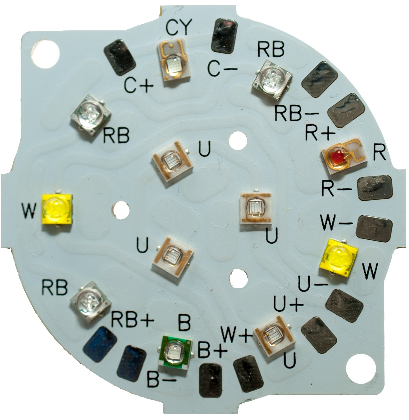
Fig 7 Rev. 1.0 of our 12x LED MCPCB
We designed this configuration based on the dimensions of a particular commercially available LED optics which can accommodate 12 LEDs densely populated within the diameter of 45mm. The assembly consisted of six independent channels:
- Violet: violet spectrum (in the 420-430nm range) comprised a significant portion of the assembly’s radiated light. We used 4pcs of the most efficient true violet LEDs at the time: Semileds N35L-U 420-430nm, 400mW up.
- White: 2pcs of cool-white, Cree XT-E (XTEHVW-Q0-0000-00000LG51)
- Royal Blue: 3pcs of Cree XT-E (XTEARY-00-0000-000000N02)
- Blue: 1pc. of Cree XP-E (XPEBLU-L1-0000-00205)
- Cyan: 1pc. of Philips Luxeon Rebel ES (LXML-PE01 Flux:K CCT:4)
- Deep Red: 1pc. of Philips Luxeon Rebel ES (LXM3-PD01-0350 Flux: D CCT: 7)
While testing these MCPCBs, following shortcomings were revealed:
- Connection of the MCPCBs required soldering skills, which was a serious disadvantage for many aquarists.
- All violet LEDs on the MCPCB were in same wavelength range. While this range was perfectly suitable for coral growth, the 420-430nm radiation was somewhat visible to the eye, similarly to the radiation of Royal Blue LEDs. This was a serious hindrance to our goal of providing coral fluorescence even while the white LEDs were ON.
- We used an MCPCB material with advanced thermal conductivity (3W/m.K), and even though we used the most efficient LEDs, this was still not sufficient for passive cooling. To avoid overheating the LEDs on this MCPCB, a heatsink with a cooler fan was required.
The second revision
The second, improved, revision was introduced on November 6, 2012. We solved all major problems of the first revision and made several important improvements:
- The proportion of violet radiation has been increased up to recommended values outlined in our article. The new version contained 5 violet LEDs with highest available efficiency, N35L-U by Semileds. The spectrum spread in violet range was extended by using 1 LED in the 390-400nm range (280mW up), 1 LED in the 400-410nm range (340mW up), 2 LEDs in the 410-420nm range (400mW up), and 1 LED in the 420-430nm range (400mW up). This helped us achieve distinct coral fluorescence even in the presence of white light, and without it being noticeable to the eye of an undesirable color tint.
- We used a novel patented MCPCB technology by SinkPAD http://www.sinkpad.com to achieve a unique thermal conductivity of 135 W/m.K: almost 50 times improvement vs. our first revision, and almost 100 times improvement vs. a standard MCPCB!
Rev. 2.0 MCPCBs looked as shown in Fig 8 below:
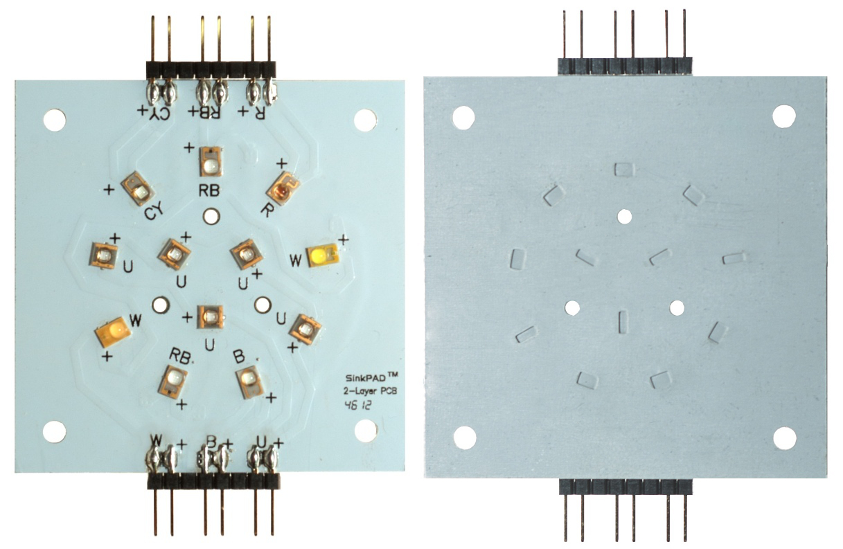
Fig 8 Front (a) and bottom (b) side of the SinkPAD MCPCB
Pay attention to the grooves on the reverse side of the metal plate: this is SinkPAD’s patented technology, responsible for the achieved extremely high thermal conductivity.
With this innovation, the new revision of our LED assembly can be used with a relatively small passive cooler: a pin-fin heatsink with the total surface area of 1050 cm.sq (about 1.13 sq.ft) at room temperature, without cooler fan, provided a comfortable temperature below 65C on LED crystals, when operated at maximum current. A thermal vision image of this study is shown in Fig 9 below:
- The MCPCB has been redesigned for solderless assembly (as a result, a larger number of hobbyists were now involved in testing).
- Cree LEDs were replaced with their even more efficient counterparts by Philips. The number of channels and spectral distribution remained the same, but one of the three Royal Blue LEDs was replaced by an additional violet LED.
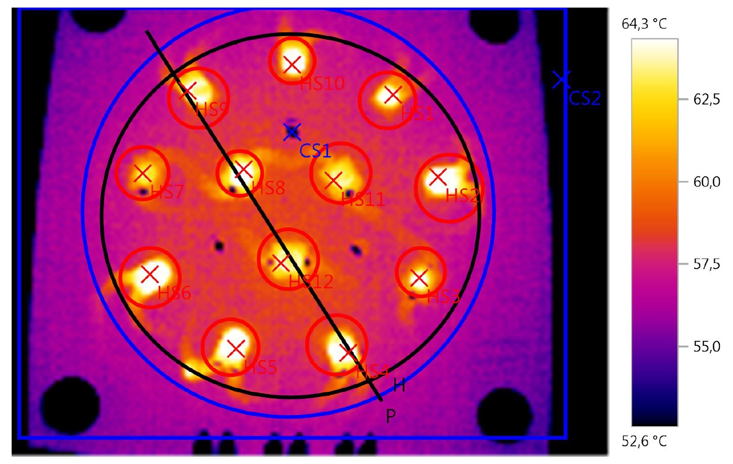
Fig 9 Thermal vision image of LEDs on SinkPAD MCPCB under maximum current
The second revision too has been tested by reefkeepers, and the following shortcomings were detected:
- The Deep Red LED betrayed our hopes in providing better reds and oranges: non-fluorescent “warm” colors in the tanks looked unnaturally cold.
- Some reefkeepers reported that an excess of deep-red radiation provoked algae growth in the tank.
On April 7, 2013 we presented an improved version of the assembly, which we call Rev. 2.1. In this revision one of the cool-white LEDs was replaced by neutral-white, and the deep-red (660nm) LED was replaced with normal red (620-630nm) Philips Luxeon LXM2-PD01-0050. This mostly resolved the problem of better representation of warm colors. To our amazement, it turned out that this orange and red spectrum added significantly to the beauty of a reef tank. This spectrum has been mostly neglected so far, and requires additional attention.
We would like to make some notes about the algae bloom concerns. Many hobbyists believe that, due to high photosynthetic activity, the presence of wavelengths longer than 620nm may facilitate to algae growth, and therefore any radiation in this range should be eliminated from the fixture. This approach will, unfortunately, deprive us from enjoying the beautiful shades of non-fluorescent orange and red color present in many corals and fish.
The algae problem can be resolved radically by maintaining good water parameters in the tank, and particularly, by maintaining constant phosphate deficiency in the water. An American oceanographer Alfred C. Redfield discovered in 1934 an empirical stoichiometric ratio of carbon, nitrogen, and phosphorus present in marine phytoplankton. It later turned out that most living organisms require these nutrients in roughly the same proportion.
However, corals are better suited to live in the conditions of phosphorus deficiency and are capable of consuming phosphorus even when it is present in minute amounts (moreover, corals obtain a significant part of required phosphorus through food, rather than in the form of dissolved in water phosphate). Lower algae require more phosphorus for growth and cannot thrive when it is lacking. Thus, by maintaining a very low phosphate (typically below 0.03ppm) and a nitrate ratio slightly exceeding the Redfield ratio over phosphate[1], i.e. in the range of 1-3ppm, algae problem in the tank can be eliminated completely.
It is worth noting that human eye’s sensitivity to red light is several times higher compared with blue light. Therefore a sensible amount of red light, sufficient for visual perception, will not be excessive compared with the relatively large amount of the available but poorly visible short-wavelength radiation. Therefore we believe that red LEDs are safe to use the, unless, of course, your tank suffers from an excess of phosphates.
On July 24, 2013 we manufactured Rev. 2.2 of our LED assembly. In the course of our continued experiments it turned out that the 390-400nm violet LED does not provide any additional fluorescence versus the LEDs radiating in the 400-410nm range. This shorter wavelength LED is less efficient, and also may cause the fluorescence of small particulate matter, giving water a milky appearance. Therefore in Rev. 2.2. we installed two LEDs in 400-410nm range, obtaining even more violet radiation (due to higher efficiency) and eliminating the above mentioned disadvantages. Rev. 2.2 also sports the newly available and highly efficient blue LED LXML-PB02 by Philips.
Thus, any evident shortcomings of the LED assembly have been eliminated, but there were certain imperfections:
- Total brightness of the LED assembly, as perceived by the eye, seemed too low, although the amount of radiated light was sufficient. This is mainly due to the fact that most hobbyists are used to the light emitted by MH or VHO bulbs which emit too much of highly visible to the eye white light.
- The representation of warmer colors of the spectrum was not ideal, and it was not possible to adjust the overall CCT towards the reduction of color temperature.
Revision Three
Rev. 3.0 of the LED assembly manufactured in September, 2013, with certain major advantages compared with the previous revisions. After thorough testing, it was announced in March, 2014.
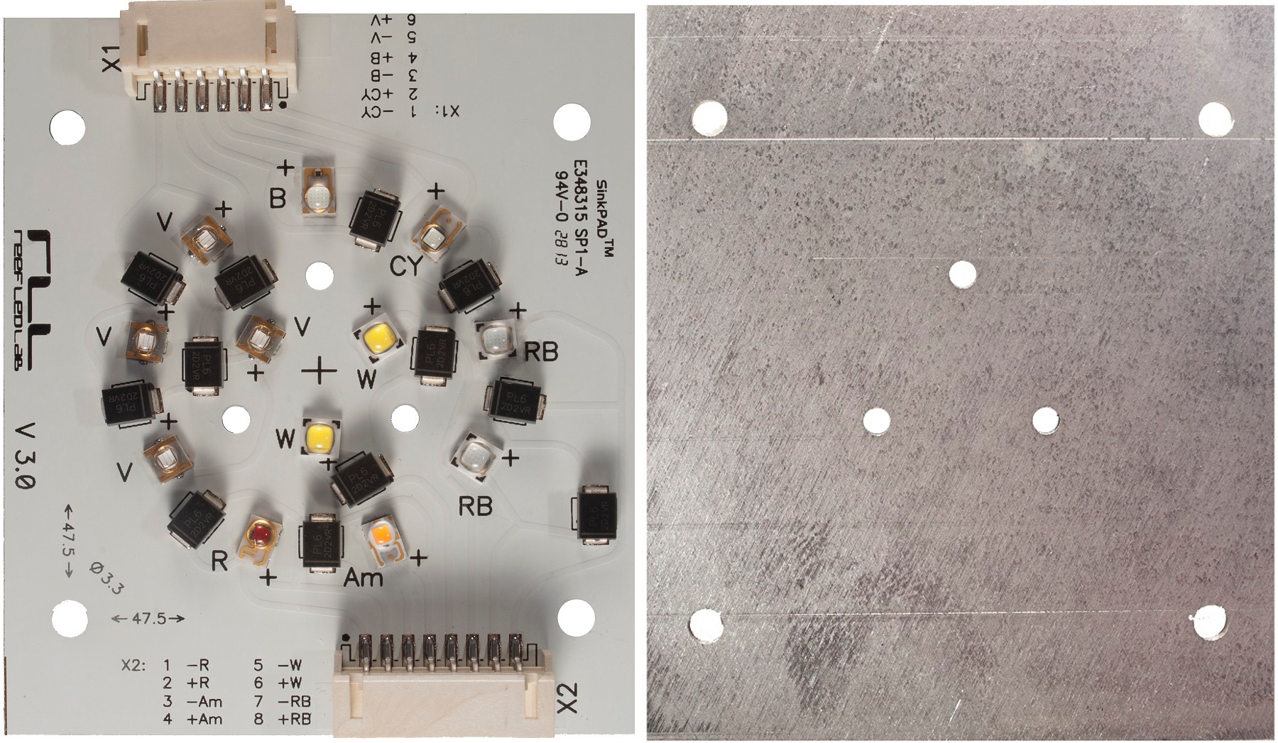
Fig 10 LED assembly Rev. 3.0
First of all, SinkPAD provided a new technology, called SinkPAD II, which allowed us to simultaneously use three different LED footprints on one MCPCB. Thus, we were able to install the newest Luxeon T range of LEDs by Philips, providing the best efficiency available today in LEDs with small crystals, along with best thermal transfer characteristics. The White and Royal Blue LEDs on our assembly can be operated close to the maximum allowed current for the LEDs thanks to the use of more efficient emitters and a shorter thermal path. By using the new advanced SinkPAD II technology, the back side of the metal plate has no grooves now, which further improves the heat transfer from MCPCB to the heatsink.
At the same time, Semileds Optoelectronics achieved a further efficiency improvement for violet LEDs, reaching over 480mW of optical radiation power at 350mA. This can be translated to at least 46% of conversion efficiency of electric power into light – a truly remarkable value for violet LEDs! This higher efficiency is now achievable in the whole range of our interest, between 410 and 430nm. Due to this efficiency increase we were able to eliminate one of the violet LEDs from the assaembly, while being able to emit even more light in the selected range: the new revision contains 1pc of 400-410nm LED, 2pcs of 410-420nm LEDs, and 1pc of 420-430nm LED.
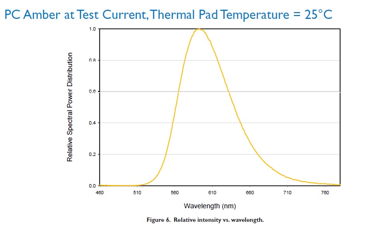
Fig 11a) Spectral distribution of radiation by PC Amber at Test Current, Thermal Pad Temperature = 25C
With the elimination of one violet LED we were able to add the seventh channel which is used for CCT control. This was possible due to the use of a unique Luxeon Rebel PC Amber LED by Philips. The spectral distribution of PC Amber (a) compared with Neutral-White (b) LED are shown in Fig 11:
Looking at the graphs, it is clear that the spectrum of PC Amber is virtually the same as with Neutral-White, except for the lack of the blue spike. The manufacturer has designed this LED specifically for the adjustment of color from cool-white LEDs, in order to achieve a warmer light.
While in our previous revisions we could only adjust the color temperature towards cooler colors (by adding the radiation of Royal Blue and True Violet LEDs), with the addition of PC Amber[2] we are now able to control the CCT towards warmer colors also. Due to using more efficient white LEDs along with PC Amber, visual brightness of our LED assembly has almost doubled!

Fig 11b) Spectral distribution of radiation by LXW8-PW35 (3500K) at Test Current, Thermal Pad Temperature = 25C
Some manufacturers try to control color warmth by using a Red-Orange (610-620nm) LED. We had experimented with this approach, but the results were not satisfactory: experienced hobbyists reported an unnatural color rendition on a reef tank. Both Red-Orange and conventional Amber LEDs emit only a narrow band in the required spectral range, whereas PC Amber has a wide and even spectral diagram in the whole range.
In Rev. 3.0 we also used a unique Philips Luxeon red LED with dominating wavelength at 630-645nm. It is better suited for our needs than the common 620-630nm, as well as the 660-670nm LEDs that were used previously. The 620-630nm range is sufficiently present in PC Amber, whereas in the 660-670nm range the sensitivity of the eye is significantly lower[3]. The use of this particular wavelength allows us to obtain an even spectral density in the long-wavelength range and to efficiently control it.
Rev. 3.0 is also equipped with SMD connectors which are more reliable and rugged than the connectors used in our previous revision. These new connectors will never come out inadvertently, even under strong vibration.
Another significant improvement in our third revision are the LED Protection Devices. These are the small black objects which you can see next to LEDs on the photograph. These devices constantly monitor the state of the attached LED. If the LED was somehow damaged, the device will make sure that operation of other LEDs in the same circuit will not be interrupted. This is an important novelty, since the LED fixture is designed for many years of operation. Even though the LEDs we use are very reliable, there are hundreds of LEDs in each fixture and there is a statistical chance that one of them will eventually die during years of operation. If each LED were not equipped with such protection, the death of one LED could result in shutting down of the whole channel.
Light Diffusers
We believe that proper light diffusers are very important part of a LED-based light fixture.
We applied serious efforts to address the “Disco effect” problem that was discussed earlier. We first tried to resolve the problem by designing a compact LED assembly with a very dense population of LEDs, each equipped with individual lenses[4]. Although the lenses helped significantly with the mixing of colors, the effect was not eliminated completely. Through extensive experimentation, we have found a suitable solution through the use of hybrid optical system.
The light from a densely populated LED assembly first passes through an efficient lens which is capable of concentrating about 93% of all emitted light into a narrow beam. This beam is then directed at a carefully selected light diffuser material which breaks it down into a very large number of smaller beams at slightly differing angles. These beams mix perfectly, forming an even distribution of all spectral components radiated by the LED assembly.
A microphotograph of the surface of the light diffusing material, designed by German Evonik specifically for color mixing purposes, is shown in Fig 12:
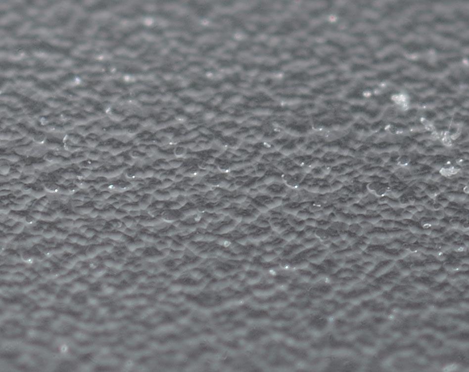
Fig 12 Microphotograph of the light-diffusing material surface
You can see on the photograph that the surface is not matte (or it would result in mere scattering and significant light loss), but consists of numerous chaotically distributed planes, providing perfect color mixing along with insignificant losses.
After passing through the diffuser, the beam becomes wider, and thus the LED fixture can be positioned comfortably at the height of 30-40cm (12-16 in) above water surface.
Our light diffusers are mounted in a ring which attaches tightly over the optics. Beside their main function, they also play another important role by protecting LEDs from particles of dust which are always present in the air and would gradually accumulate on the LED’s primary optics and the adjacent part of secondary optics. Initially, this dust is negligible, but over years of fixture’s operation primary optics will start absorbing light. This, in turn, would result in the overheating of the LEDs. The attached diffuser ring can be glued to the MCPCB, thus hermetically sealing the whole assembly, Fig 13.
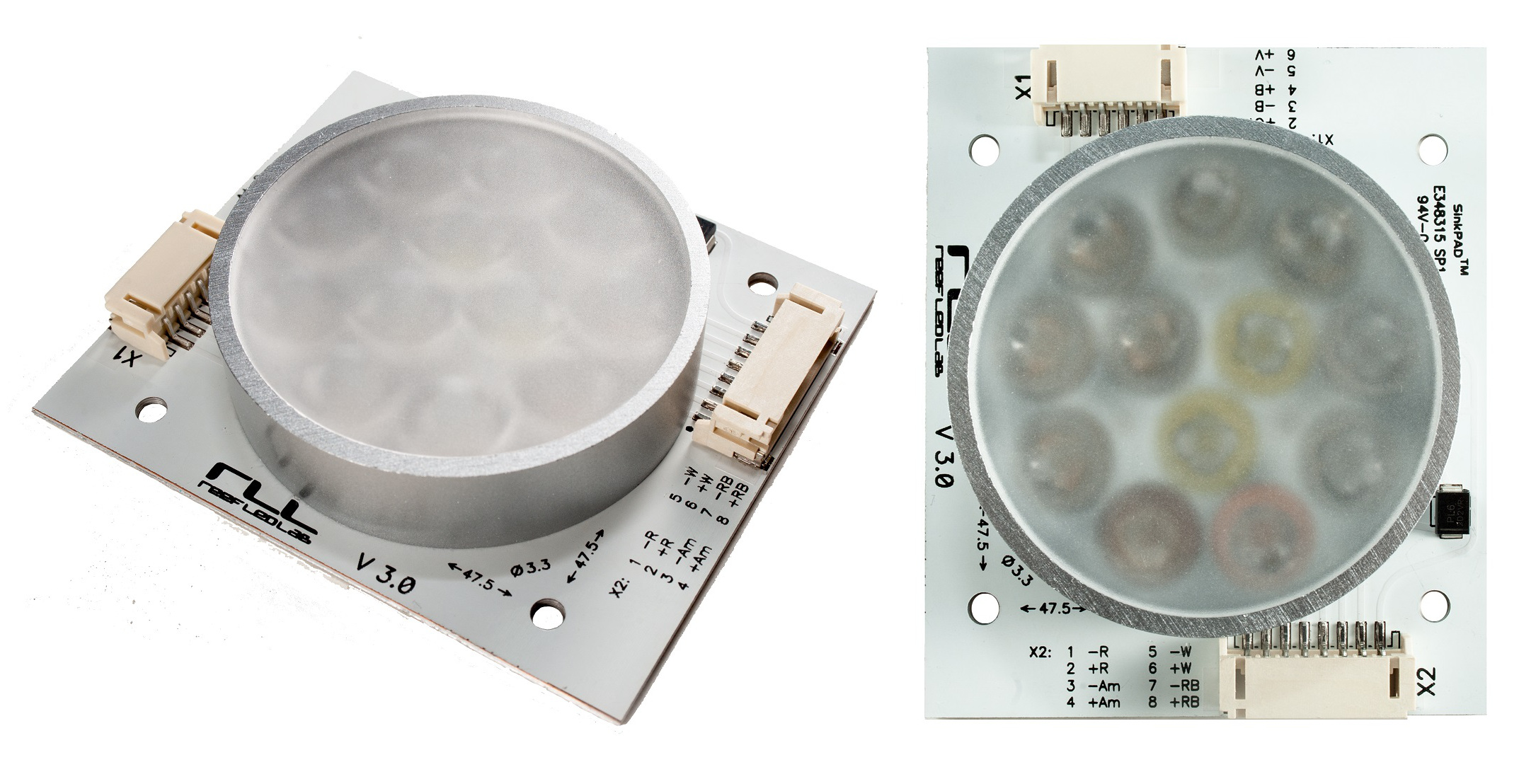
Fig 13 Light diffuser with sealing ring, attached to the assembly
Acknowledgements
We would like to thank the many enthusiasts at Russian reefkeeping forums http://www.aqualogo.ru/phpbb2/ and http://reefcentral.ru/forum/ who tested the consecutive revisions of our LED assemblies on their reef tanks. Without their help and invaluable discussions, our work would not have been successful.
Unfortunately we cannot list everyone by the name here, but we would particularly like to mention Karen Sanamyan for the experiments with visual perception of red spectrum and testing out the diffuser materials, Egidijus Juteika for the experiments with visual perception of numerous SPS corals under different spectra generated by our LED assembly, Oleg Dubinsky for help in all matters concerning electronics, Roman Piontik for analytical representation of the LED assembly’s spectrum in various modes, Vladimir Juma for optimal representation and systematization of materials under study, and Oleg Tkachev for advice concerning red spectral range. They, along with many other unlisted enthusiasts, helped us immensely in testing out the results of our work, pointing at any flaws witnessed during operation, and participating in discussions concerning the approaches towards their elimination. It is due to their efforts, observations, recommendations and friendly help, that we were able to advance our project on building an optimal LED assembly.
Among all other LED manufacturers we would like to particularly acknowledge Semileds Optoelectronics for their unending support to our numerous requests and continuous refinements, and their invaluable professional consultations on very many issues. Our every whim was taken very seriously, and they continue doing their best to provide us with the best options possible. It is mostly due to this cooperation that we were able to represent the important violet spectrum in our product fully in accordance with our understanding of its requirements.
References
1.Wikipedia: Color vision [http://en.wikipedia.org/wiki/Color_vision]
2.Redfield’s Ratio Refuted [http://www.enn.com/wildlife/article/45744]
[1] According to the recently corrected Redfield ratio [2], in warm, nutrient-starved areas the algae requires for growth the Nitrogen:Phosphorus atomic ratio of 28:1. If we recalculate this to NO3:PO4, the ratio is approximately 18:1
[2] Note that PC Amber is a unique LED, manufactured exclusively by Philips Lumileds at the time of writing this article. This LED is quite different from the widely available Amber LED (with wavelengths around 590nm) offered by many manufacturers. In the name of this LED, PC stands for Phosphor-Converted. This is a InGaN based LED coated with special Lumiramic phosphor, which gives up to 4-5 times the light output of conventional AlInGaP amber products. Beside this huge efficiency benefit, conventional amber LEDs are very sensitive to overheating – their efficiency drops by hefty 50% at crystal temperatures of just 60-70C – which is otherwise a quite comfortable temperature for all other LEDs on the assembly.
[3] To make it more visible, significant power should be radiated. This light being extremely photosynthetically active, it might result in potential algae problems if the phosphate level in not properly controlled.
[4] Even the use of custom COBs, where differently colored LEDs come in bands, does not fully solve this problem, whereas the design of a COB with fully mixed-up placement of multicolored LEDs is too complicated technologically.
0 Comments